Shaped Charges for Creating Enhanced Perforation Tunnel in a Well Formation

a well formation and perforation tunnel technology, applied in the field of perforating tools, can solve problems such as affecting the flow of oil into the well casing

Active Publication Date: 2006-11-30
SCHLUMBERGER TECH CORP
View PDF30 Cites 102 Cited by
  • Summary
  • Abstract
  • Description
  • Claims
  • Application Information

AI Technical Summary

Benefits of technology

[0028] Referring to FIG. 3, the material from the collapsed liner 23 forms a perforating jet 31 that shoots through the front of the shaped charge and penetrates the casing 12 and underlying formation 16 to form a perforated tunnel (or perforation tunnel) 42 (see FIG. 4). Referring to FIG. 4, around the surface region adjacent to the perforated tunnel 42, a layer of the formation (e.g., carbonate rock) is usually damaged or crushed by the shock wave. This damaged layer 43 may have a reduced permeability such that subsequent productivity of hydrocarbons is reduced.
[0030] For example, if the formation is a carbonate formation, then the damaged layer may be decomposed under thermal heating at relatively low temperatures. By using a liner formulation that reacts with the carbonate formation to generate heat within the perforated tunnel, the damaged layer may be removed. As a result, the perforated tunnel may be cleaned such that permeability of the target well zone can be increased at the tunnel surface region. Moreover, in some embodiments, the thermal stress created by the exothermic reaction between the liner material and the carbonate formation may also induce additional fractures in the formation radiating from the perforated tunnel, as illustrated in FIG. 5. These fractures may further increase permeability of the formation and subsequent productivity of the target well zone.
[0040] In accordance with some embodiments of the invention, the materials selected to fabricate the liner may not have sufficiently high densities to penetrate the casing and / or underlying formation, yet they may yield high exothermic heat energy when they react. In this case, the reactant materials may be combined with a denser component (e.g., tungsten, copper, lead, or others, or a combination thereof) to enhance penetration depth.
[0048] These reactions are exothermic and can generate a lot of heat. The heat not only will increase the reactants' temperature and accelerate the reaction rates, but may also cause the formation to decompose. The reaction and heat generated facilitate cleaning of the perforated tunnel and thus increase productivity. Moreover, in some cases, the damaged zone may be totally reacted and decomposed such that even some of the virgin rock is reacted due to the large amount of heat released by these reactions. When this occurs, the effects are two fold: (1) the damaged zone is cleaned up, and (2) the perforation tunnel is enlarged in diameter, which in turn can significantly reduce pressure drop for viscous flows and thus enhance productivity.
[0050] Uranium, while not necessarily as reactive as other light metals mentioned above (releasing only approx. 2.15 KJ / gm with CaCO3), has a relatively high density (approx. 18.97 g m / cc) and can thus produce deeper penetration and deliver a higher shock pressure, which may also assist carbonate decomposition.

Problems solved by technology

One problem often encountered in perforation operations is that the slug from a molten liner of a shaped charge may be embed in the perforated hole (tunnel), impeding the flow of oil into the well casing.

Method used


Image

  • Shaped Charges for Creating Enhanced Perforation Tunnel in a Well Formation
  • Shaped Charges for Creating Enhanced Perforation Tunnel in a Well Formation
  • Shaped Charges for Creating Enhanced Perforation Tunnel in a Well Formation

Examples


Embodiment Construction

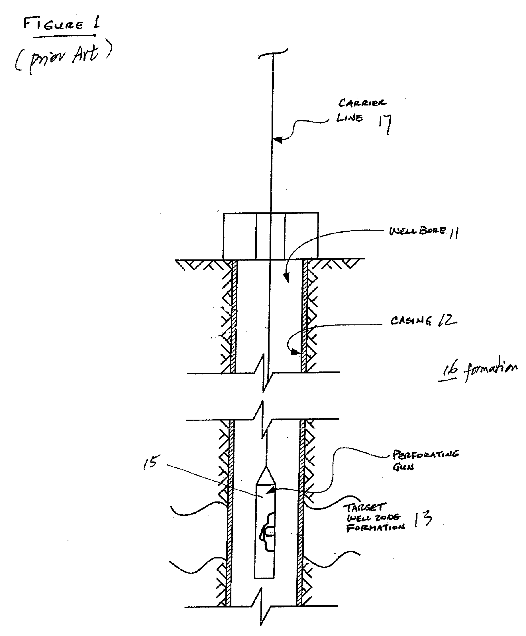
[0025] Embodiments of the invention relate to shaped charges and methods used in perforating a well, cased or not cased. In the following description, numerous details are set forth to provide an understanding of the present invention. However, it will be understood by those skilled in the art that the present invention may be practiced without these details and that numerous variations or modifications from the described embodiments may be possible.

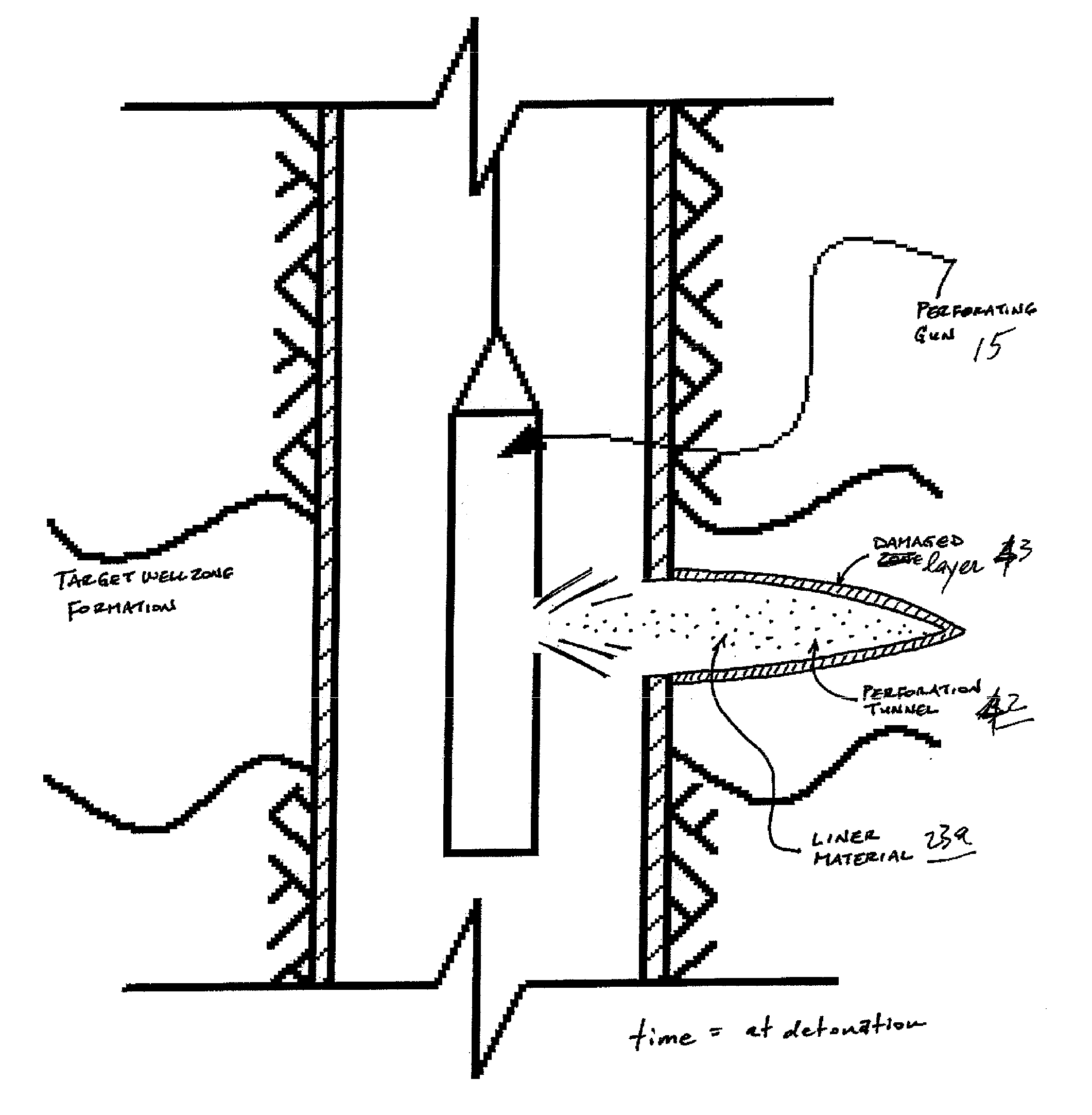
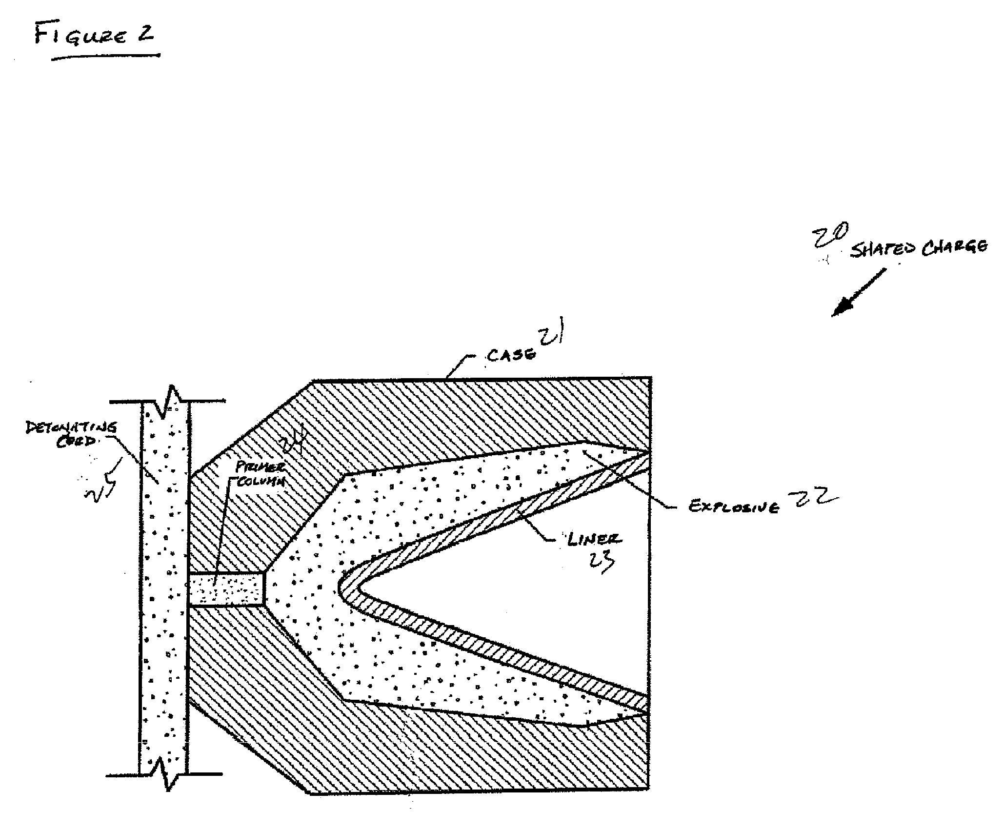
[0026] Referring to FIG. 2, a shaped charge 20 in accordance with embodiments of the present invention includes an outer case (a charge case) 21 that acts as a containment vessel designed to hold the detonation force of the detonating explosion long enough for a perforating jet to form. Materials for making the charge case may include steel or other sturdy metals. The main explosive charge (explosive) 22 is contained inside the charge case 21 and is arranged between the inner wall of the charge case and a liner 23. A primer column 24 (o...


PUM


Abstract

A shaped charge includes a charge case; an explosive disposed inside the charge case; and a liner for retaining the explosive in the charge case, wherein the liner comprises a material reactive with a component of an earth formation. A method for perforating in a well includes disposing a perforating gun in the well, wherein the perforating gun comprises a shaped charge having a charge case, an explosive disposed inside the charge case, and a liner for retaining the explosive in the charge case, wherein the liner includes a material that can react with a component of an earth formation; detonating the shaped charge to form a perforation tunnel in a formation zone; and allowing the material comprising the liner to react with the component of the earth formation.

Description

DESCRIPTION [0001] Cross-Reference To Related Applications. The present application claims priority of U.S. Provisional Patent Application Ser. No. 60 / 594,997 filed on May 25, 2005. This Provisional Application is incorporated by reference in its entirety.BACKGROUND OF INVENTION [0002] Field of the Invention. The present invention relates generally to perforating tools used in downhole applications, and more particularly to shaped charges for creating an enhanced perforation tunnel in a target formation zone in a well. BACKGROUND ART [0003] To complete a well, one or more formation zones adjacent a wellbore are perforated to allow fluid from the formation zones to flow into the well for production to the surface or to allow injection fluids to be applied into the formation zones. A perforating gun string may be lowered into the well and one or more guns fired to create openings in casing and to extend perforations into the surrounding formation. [0004] With reference to FIG. 1, afte...

Claims


Application Information

Patent Timeline
Patent Type & Authority Applications(United States)
IPC IPC(8): E21B43/11E21B7/00
CPCE21B43/117E21B43/116
Inventor YANG, WENBOBEHRMANN, LAWRENCE A.
Owner SCHLUMBERGER TECH CORP
Why Eureka
Try Eureka