Power charging device with charge saturation disconnector through electromagnetic force release

Active Publication Date: 2012-09-18
YANG TAI HER
View PDF4 Cites 10 Cited by
  • Summary
  • Abstract
  • Description
  • Claims
  • Application Information

AI Technical Summary

Benefits of technology

[0062]FIG. 1 is a structural drawing showing the main components of the present invention.
[0009]FIG. 2 is a structural drawing showing an embodiment of FIG. 1 applied to the rechargeable discharge device (104) with a conductive structure installed on one side;

Problems solved by technology

Typically, a rechargeable device is placed within a power charging device and stays in a same position even after charge saturation, which often leads to overcharge.

Method used


Image

  • Power charging device with charge saturation disconnector through electromagnetic force release
  • Power charging device with charge saturation disconnector through electromagnetic force release
  • Power charging device with charge saturation disconnector through electromagnetic force release

Examples


Embodiment Construction

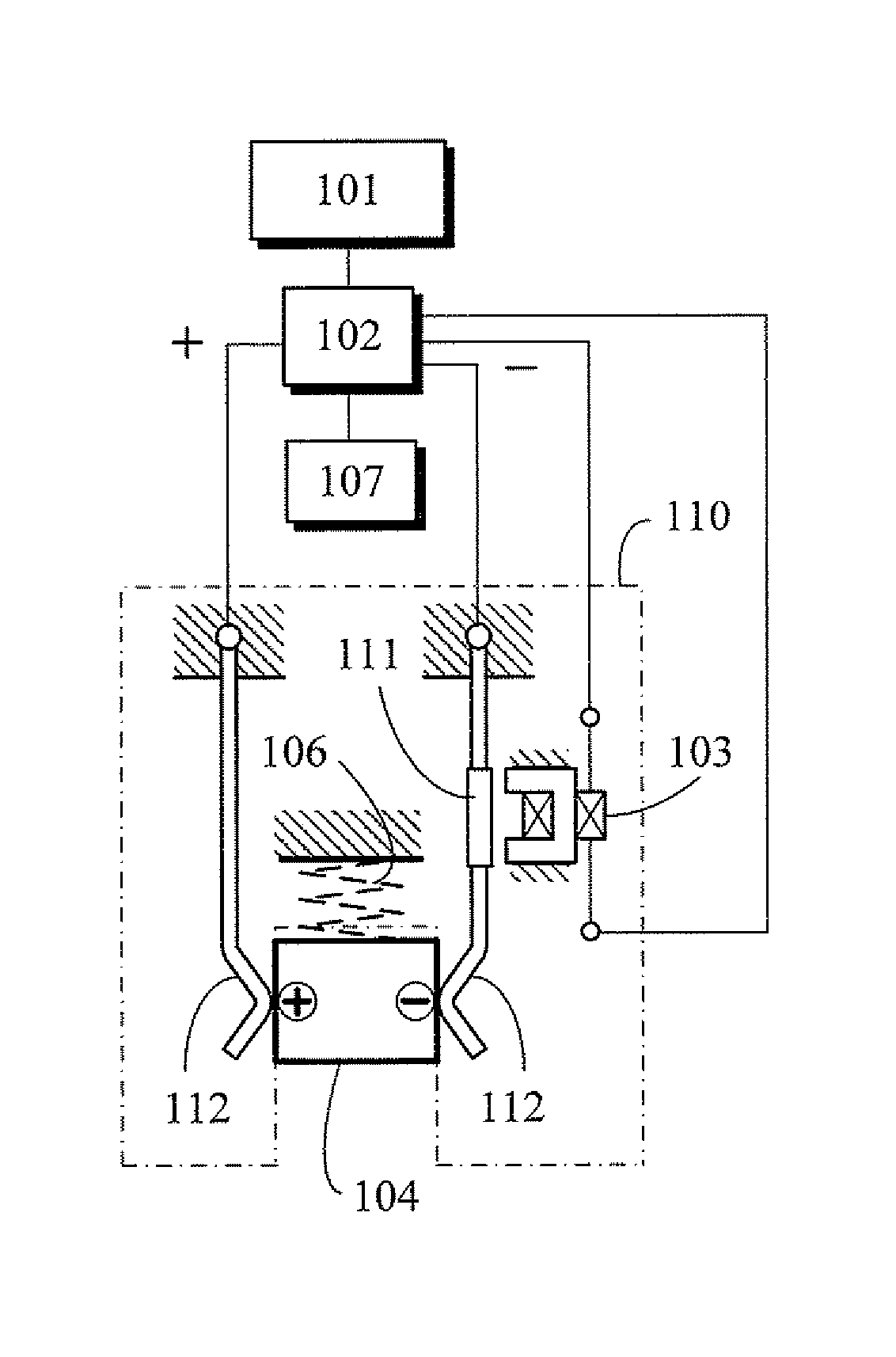
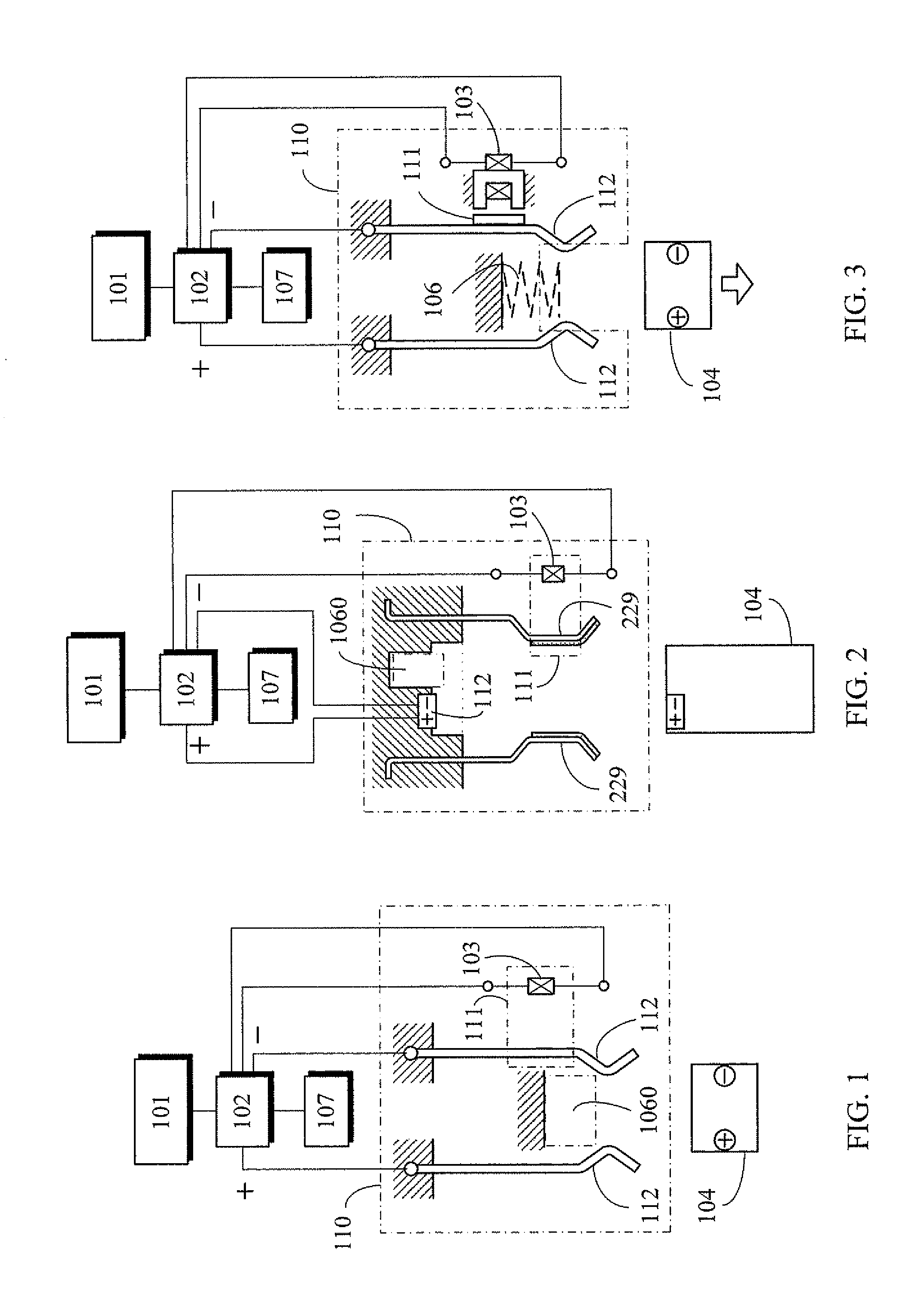
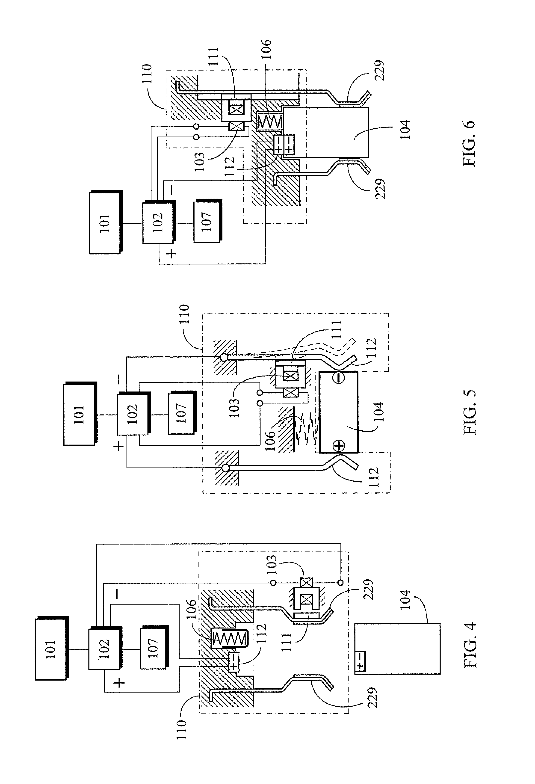
[0061]A power charging device with a charge saturation disconnector that operates through electromagnetic force release is formed by a charging power supply, charging control device, magnetic actuator conductive device, power excitation windings, rechargeable discharge device, and various detection devices optionally provided as needed for detection of the charge situation of the rechargeable discharge device.

[0062]FIG. 1 is a structural drawing showing the main components of the present invention.

[0063]As showed in FIG. 1, the power charging device with charge saturation disconnector through electromagnetic force release transmits power energy from a charging power supply (101) to charging control device (102), and then under the control of the charging control device (102) transmits the power energy to magnetic actuator conductive device (110) for charging rechargeable discharge device (104) clamped by conductive device (112) installed within the magnetic actuator conductive devic...


PUM

PropertyMeasurementUnit
charging voltageaaaaaaaaaa
currentaaaaaaaaaa
power energyaaaaaaaaaa

Abstract

A power charging device with charge saturation disconnection through electromagnetic force release is formed by a charging power supply, charging control device, a magnetic actuator conductive device, power excitation windings, a rechargeable discharge device, and various detection devices provided for detection of the charge situation of the rechargeable discharge device.

Description

BACKGROUND OF THE INVENTION[0001](a) Field of the Invention[0002]The present invention relates to a power charging device, in which a rechargeable device is placed within a magnetic actuator conductive device of the power charging device, and in which the rechargeable device is disconnected from the magnetic actuator conductive device when the rechargeable device attains charge saturation.[0003](b) Description of the Prior Art[0004]Typically, a rechargeable device is placed within a power charging device and stays in a same position even after charge saturation, which often leads to overcharge.SUMMARY OF THE INVENTION[0005]A power charging device with a charge saturation disconnector utilizing electromagnetic force release is formed by a charging power supply, a charging control device, a magnetic actuator conductive device, power excitation windings, a rechargeable discharge device, and various detection devices optionally provided as needed for detection of the charge situation of...

Claims


Application Information

Patent Timeline
Patent Type & Authority Patents(United States)
IPC IPC(8): H01M10/46
CPCH02J7/0042H02J7/00H02J7/0036H01M10/443Y10S482/903
Inventor YANG, TAI-HER
Owner YANG TAI HER
Why Eureka
Try Eureka