
Enhanced drop mixing using magnetic actuation

a drop mixing and magnetic actuation technology, applied in the direction of flow mixers, positive displacement liquid engines, chemical/physical/physical-chemical stationary reactors, etc., can solve the problem that the literature has not revealed an apparatus, method or system appropriate for the uses addressed

Inactive Publication Date: 2011-10-27
PALO ALTO RES CENT INC
View PDF24 Cites 11 Cited by
  • Summary
  • Abstract
  • Description
  • Claims
  • Application Information

AI Technical Summary

Benefits of technology

The patent describes a method and device for mixing two separate fluid drops on a substrate. The device includes a surface area where magnetic material is placed. The first fluid drop is then placed on top of the magnetic material, causing the magnetic material to be partially positioned inside the fluid drop. The second fluid drop is then placed on top of the first fluid drop. A magnetic field is applied to the area where the drops are merging, causing the magnetic material to move and stir the fluid. A force is also applied to bring the two fluid drops together and enhance the mixing of their constituents. The technical effect is a more effective and efficient mixing of fluid drops on a substrate.

Problems solved by technology

However, the literature has not revealed an apparatus, method or system appropriate for the uses addressed in this application.

Method used


Image

  • Enhanced drop mixing using magnetic actuation
  • Enhanced drop mixing using magnetic actuation
  • Enhanced drop mixing using magnetic actuation

Examples


Embodiment Construction

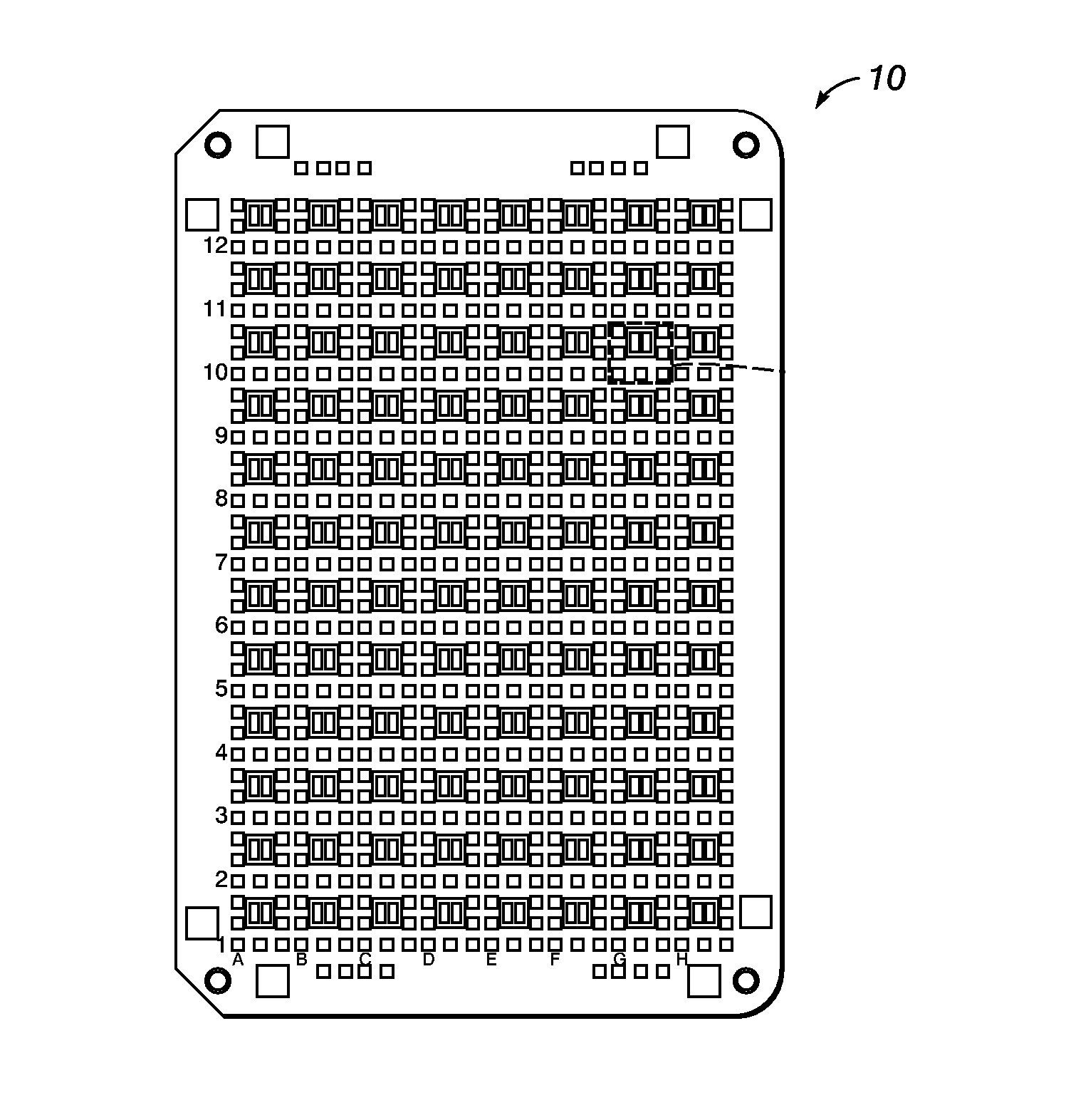
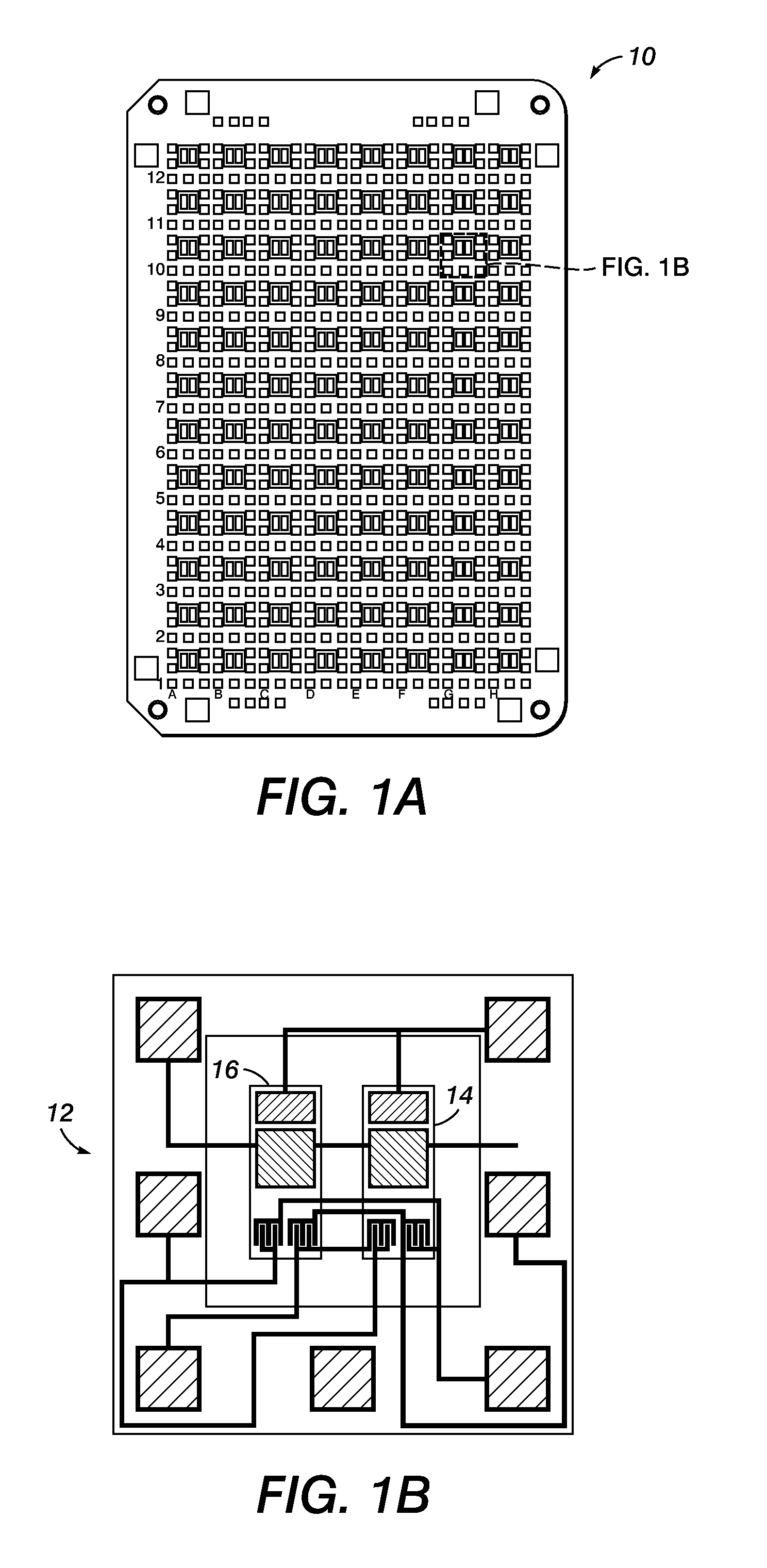
[0026]Turning to FIG. 1A, illustrated is an example of an enthalpy array 10 having a plurality of nanocalorimeter detector cells 12 which enable efficient biological research and drug discovery through direct measurement of molecular interaction. Such arrays can be fabricated using microfabrication technology in a 96-detector format and interface with automated laboratory equipment.

[0027]As expanded on in FIG. 1B, each detector 12 consists of two identical adjacent sensing regions 14, 16 that provide a differential temperature measurement—one for a sample and one for a reference specimen. Each region is equipped with two thermistors, the four thermistors are combined in an interconnected Wheatstone bridge, and each region also has its own isothermal merging and mixing mechanism that is electrostatically driven. The thermistors may be made from vanadium oxide, amorphous silicon, or other appropriate material. In this description isothermal refers to the fact that the amount of heat g...


PUM

PropertyMeasurementUnit
diameteraaaaaaaaaa
diameteraaaaaaaaaa
diameteraaaaaaaaaa

Abstract

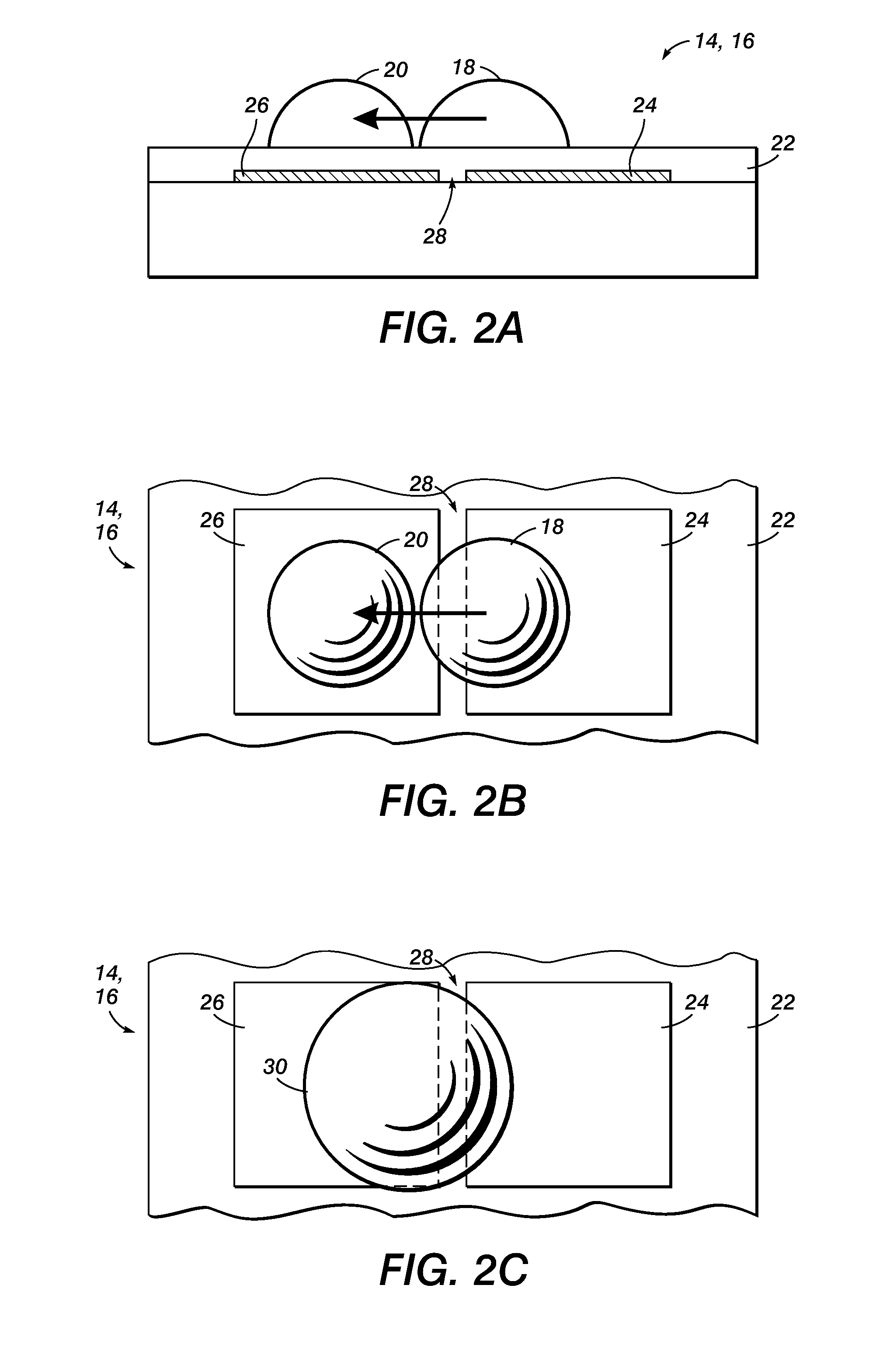
A method and device for merging and mixing at least two separate and distinct fluid drops on a substrate, includes a drop merging area on the surface, where a first magnetic material is placed at a first location. A first drop of fluid is then placed at the first location on the surface, resulting in the first magnetic material being at least partially positioned within the first drop of fluid. A second drop of fluid is then placed at a second location on the surface of the drop merging area. A magnetic field is applied by a varying magnetic field generator to at least a portion of the drop merge area of the substrate, which includes at least the first location on the substrate. The varying magnetic field will act on the first magnetic material to move the first magnetic material within the first drop of fluid, causing a stirring of the fluid. A drop merging force from a drop merging mechanism is applied to at least one of the first drop of fluid and the second drop of fluid within the drop merge area. This causes at least one of the first drop of fluid and the second drop of fluid to move toward the other and make contact. The internal stirring of the fluid in the first drop of fluid by the movement of the magnetic material enhances the mixing of the constituents of the first drop of fluid and the constituents of the second drop of fluid.

Description

STATEMENT REGARDING FEDERALLY SPONSORED RESEARCH OR DEVELOPMENT[0001]The U.S. Government has a paid-up license in this invention and the right in limited circumstances to require the patent owner to license others on reasonable terms as provided by the terms of Contract No. 1 R01 GM077435-01 awarded by National Institute of Health (NIH).BACKGROUND[0002]This application relates to the merging and mixing of individual drops of fluid, both in small numbers and in arrays. More specifically, the application provides apparatuses, methods and systems for placing drops on a surface and moving, merging and mixing the drops of fluid across the surface through use of electrostatic actuation, magnetic actuation or other mechanisms.[0003]Mixing of fluid by use of magnetic mixers is a known process. Research in this area has included the use of MEMS technology to demonstrate enhanced micro-scale mixing (see, Lu, Ryu and Liu in Journal of Microelectromechanical Systems, Vol. 11, No. 5, October 200...

Claims


Application Information

Patent Timeline
Patent Type & Authority Applications(United States)
IPC IPC(8): C40B60/14F15D1/00
CPCB01F13/0076B01F13/0071Y10T436/25B01F13/0818B01F13/0077B01F2015/0221Y10T436/2575G01N25/48Y10T137/0318Y10T137/87652B01F33/3032B01F33/3021B01F33/3031B01F33/452B01F35/715
Inventor DE BRUYKER, DIRKBHAGAT, ALI ASGARBELL, ALAN G.RECHT, MICHAEL I.TORRES, FRANCISCO E.
Owner PALO ALTO RES CENT INC
Learn More