Magnetic actuator drive for actuation and resetting of magnetic actuation materials

a magnetic actuator and drive technology, applied in the direction of generator/motor, magnetic body, device details, etc., can solve the problems of actuation stroke, magnetic actuation system, and release of developed actuation strain, and achieve the effect of expanding the range of applications

Inactive Publication Date: 2007-05-15
MASSACHUSETTS INST OF TECH
View PDF9 Cites 11 Cited by
  • Summary
  • Abstract
  • Description
  • Claims
  • Application Information

AI Technical Summary

Benefits of technology

[0011]The invention overcomes the limitations of conventional magnetic actuation systems to provide a magnetic actuator that can be implemented as a small, light-weight, and compact actuator, requiring only a comparatively small power source. These characteristics greatly expand the range of applications of magnetic material actuation.
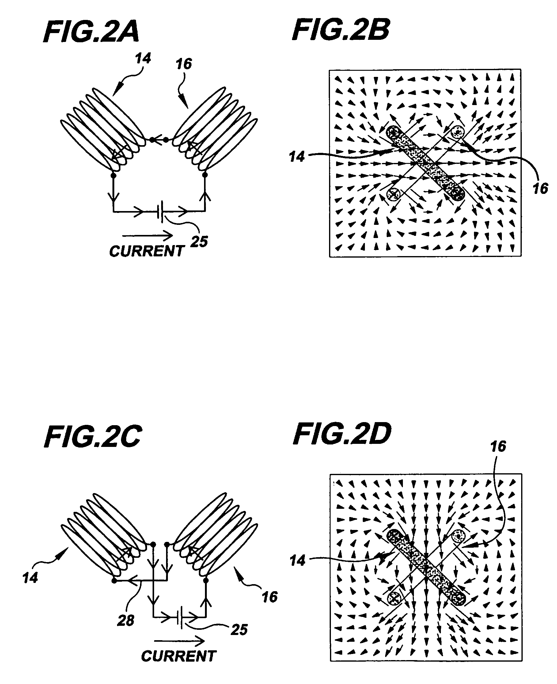
[0014]The magnetic actuator and actuation techniques provided by the invention can be applied to a wide range of configurations and materials, including, e.g., ferromagnetic shape memory materials and magnetostrictive materials. Additionally, DC, AC, pulsed, or other current flow control can be employed for generating a magnetic field with the coil configuration. This enables a high degree of control for actuating and resetting magnetic materials in an actuation cycle.

Problems solved by technology

This twin variant growth results, on a macroscopic scale, in a shape change of the FSMA material, leading to an actuation stroke.
This results in release of the developed actuation strain.
The resulting magnetic actuation systems, tending to be large, weighty and cumbersome, cannot meet the needs of many important actuation applications.

Method used


Image

  • Magnetic actuator drive for actuation and resetting of magnetic actuation materials
  • Magnetic actuator drive for actuation and resetting of magnetic actuation materials
  • Magnetic actuator drive for actuation and resetting of magnetic actuation materials

Examples


Embodiment Construction

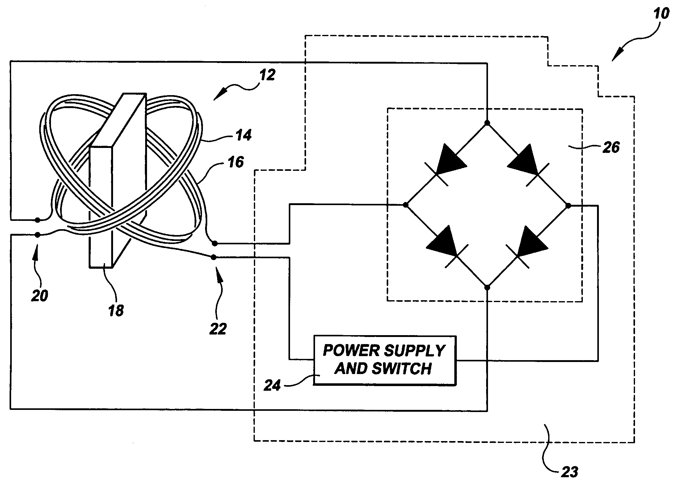
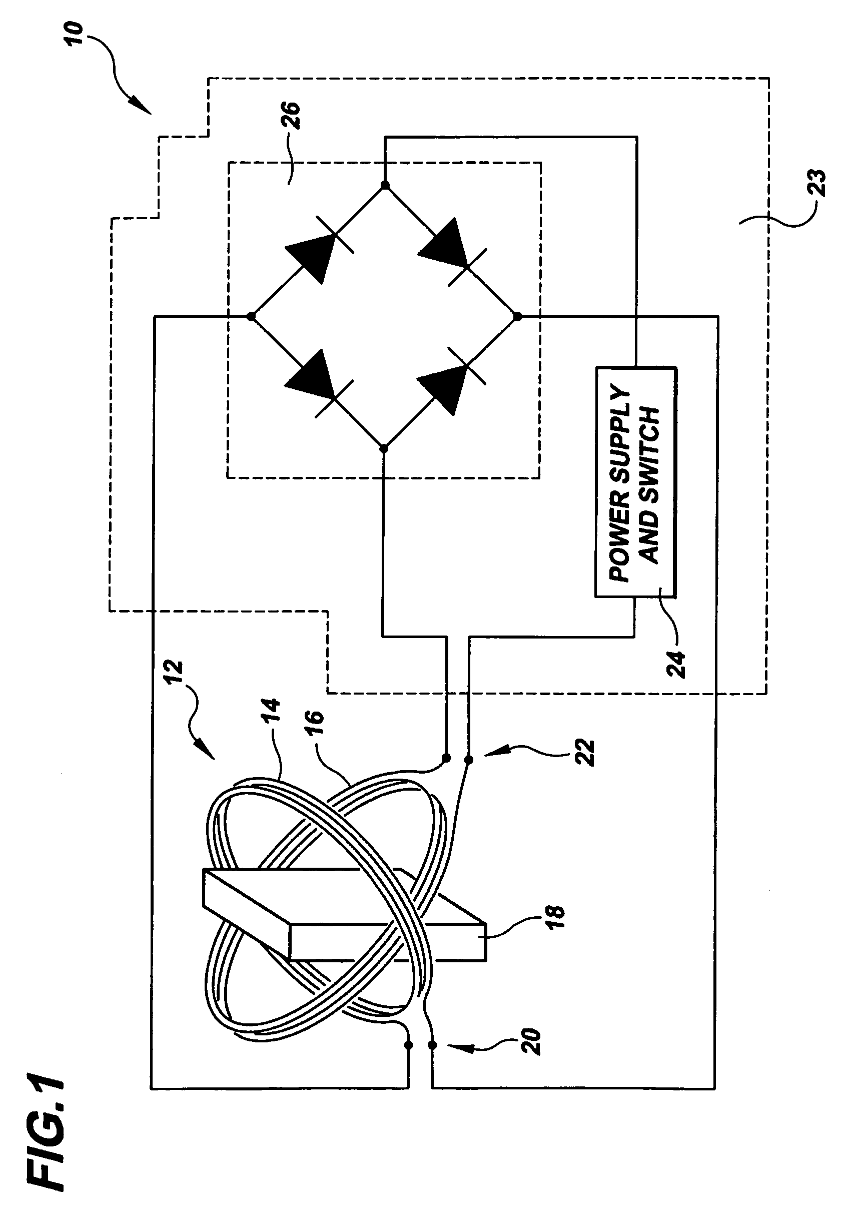
[0040]Referring to FIG. 1, there is shown a schematic view of an example embodiment 10 of the magnetic actuator of the invention. The actuator 10 includes a magnetic actuator drive 12 having a plurality of electrically conducting coils. The example actuator of FIG. 1 includes two coils 14, 16, each with a selected number of wire turns, but any suitable number of coils can be employed. The plurality of coils are interconnected in a suitable configuration, e.g., a series configuration, parallel configuration, or combination series-parallel configuration, in an electrical circuit with associated actuator drive components, described in detail below.

[0041]The coils 14, 16 are arranged so that a magnetic field-actuated material 18 to be actuated can be positioned within or sufficiently close to the coil configuration to be coupled to a magnetic field generated by the passage of current through the coils. Preferably the coils are arranged with air cores and a common center to the coils, bu...


PUM

PropertyMeasurementUnit
lead resistanceaaaaaaaaaa
actuation frequencyaaaaaaaaaa
thicknessaaaaaaaaaa

Abstract

A magnetic actuator is provided including a magnetic field-actuated material and a plurality of interconnected electrically conducting coils, each coil including a number of wire turns arranged relative to at least one other coil to produce at the magnetic field-actuated material, by superposition, a magnetic field that is substantially oriented in one of a plurality of selectable discrete directions. An actuator drive circuit is connected to the coils in a circuit configuration that reverses a direction of electrical current flow through at least one of the coils to reorient the magnetic field from a first selected direction to a second selected direction of the plurality of selectable discrete directions.

Description

[0001]This application claims the benefit of U.S. Provisional Application No. 60 / 559,702, filed Apr. 5, 2004, the entirety of which is hereby incorporated by reference.STATEMENT REGARDING FEDERALLY SPONSORED RESEARCH[0002]This invention was made with Government support under Contract No. N00014-01-1-0758, awarded by the Office of Naval Research. The Government has certain rights in the invention.BACKGROUND OF THE INVENTION[0003]This invention relates to magnetic actuators, and more particularly relates to methods for generating actuation with magnetic field-actuated materials.[0004]Magnetic actuation is an increasingly important actuation technique for a wide range of applications. There have been identified and developed a number of magnetic materials that produce large actuation strain, as well as appreciable actuation force, with rapid actuation frequency. Such attributes address common requirements of many modern applications for which hydraulic, pneumatic, electrostatic or elec...

Claims


Application Information

Patent Timeline
Patent Type & Authority Patents(United States)
IPC IPC(8): H02N2/00H01L41/12H01F1/03H01F1/055H01F7/08H01L41/06
CPCH01F1/0306H01L41/06H01L41/12H01F1/055H10N35/80H10N35/00
Inventor MARIONI, MIGUEL A.
Owner MASSACHUSETTS INST OF TECH
Why Eureka
Try Eureka