Eureka AIR delivers breakthrough ideas for toughest innovation challenges, trusted by R&D personnel around the world.

Boat speed control

a technology for controlling the speed of boats and boats, which is applied in the direction of waterborne vessels, marine propulsion, vessel construction, etc., can solve the problems of not ensuring the constant speed of boats, and achieve the effects of stable and predictable control of the speed of boats, high degree of control, and quick respons

Inactive Publication Date: 2003-02-06
INTO STEPHEN W
View PDF7 Cites 29 Cited by
  • Summary
  • Abstract
  • Description
  • Claims
  • Application Information

AI Technical Summary

Benefits of technology

[0011] The method further includes detecting an actual speed of the motor, generating a second input representative of the actual speed of the motor, and generating an output, on the basis of the first input and the second input, to minimize the difference between the first input and the second input. Among other advantages, the control system provides for stable and predictable control of the speed of a boat. With this arrangement, the control system and its method of operation allows the operator to maintain the speed of the boat or motor without having to repeatedly adjust the hand lever. The control system can be interfaced to an existing standard boat control such that little or no training is required to learn the operation of the control system since the user interface is similar to standard controls. The control system can be used at all boat speeds, including very slow speeds. The control system can also be installed on standard locations on the boat without the need for much additional hardware mounting space. The cascaded loops allow fast servo loop response to maintain steady RPM control, while the slower boat speed control loop adjusts the desired RPM. This makes it possible to have quick response and a high degree of control.

Problems solved by technology

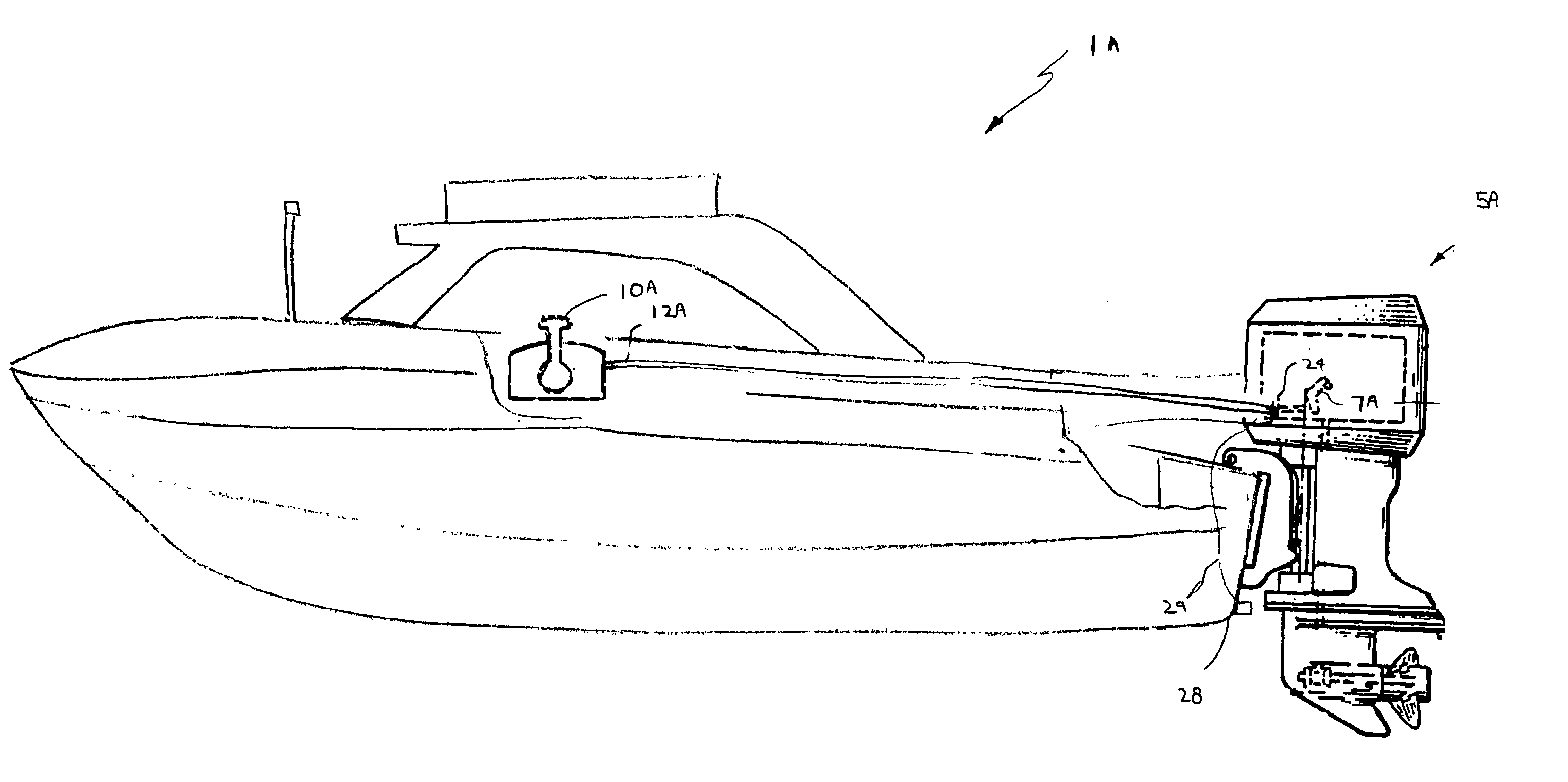
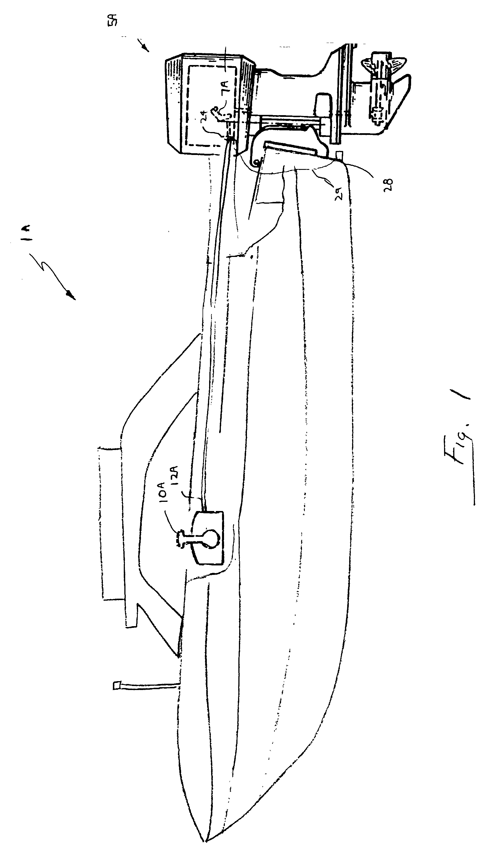
Manually positioning the throttle lever 10A, however, does not ensure that the speed of the boat is constant.

Method used


Image

  • Boat speed control
  • Boat speed control
  • Boat speed control

Examples


Embodiment Construction

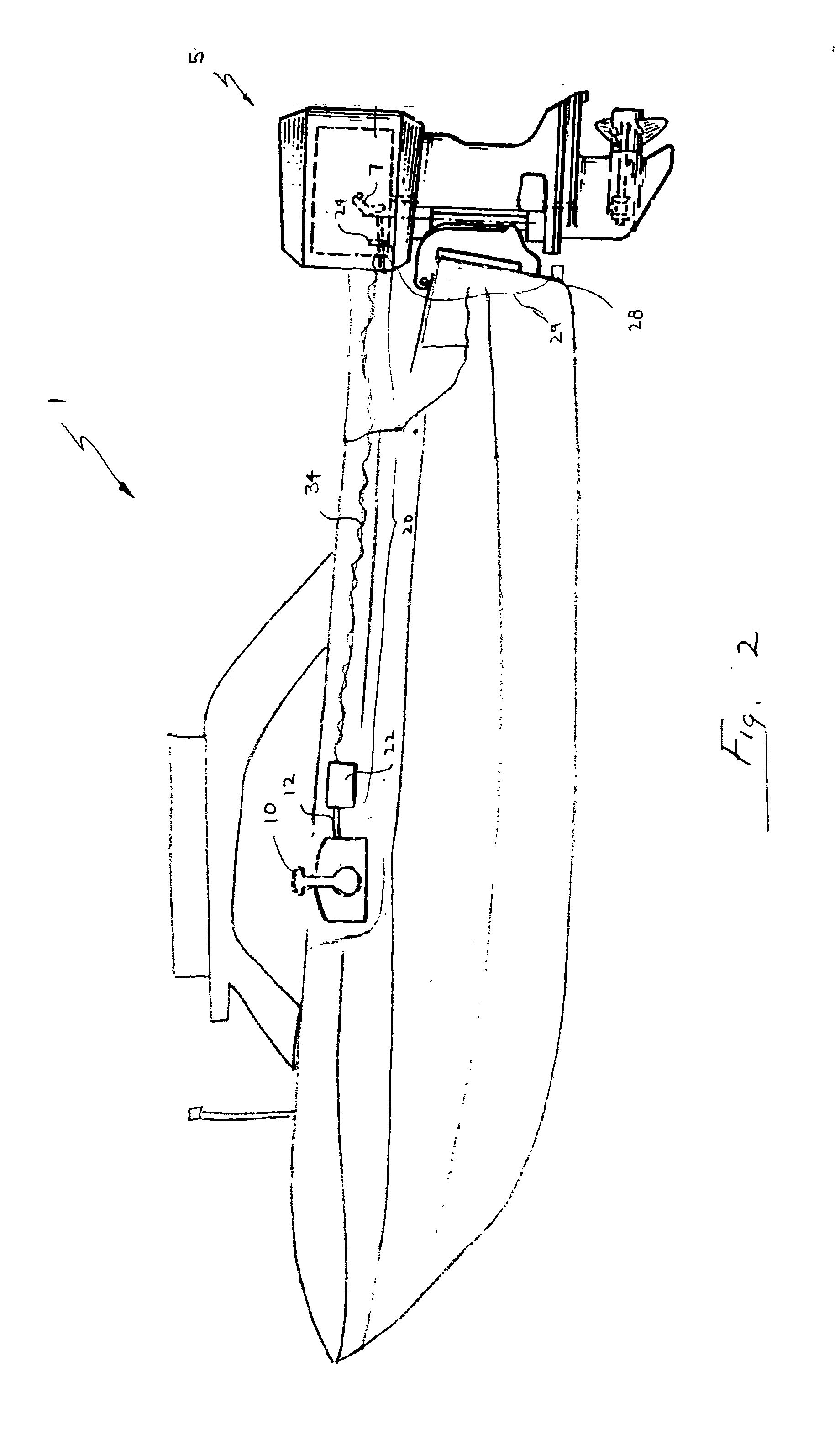
[0019] Referring to FIG. 2, a boat 1 includes a motor 5 mounted to the stem of the boat and a throttle 7 for regulating the speed of the motor. Within the cockpit area of boat 1 is a throttle lever 10, which is connected to throttle 7 through speed control system 20.

[0020] As will be described in greater detail below, speed control system 20 provides for improved operator control of the speed of boat 1 without having to repeatedly adjust throttle lever 10. In this embodiment, speed control system 20 is shown having a first housing 22 positioned adjacent to throttle lever 10 and having a position sensor 30 (FIG. 3) electrically connected, via wiring 34, to a controller 32 (FIG. 3) mounted within a second housing 24 mounted near throttle 7. In a particular embodiment, boat 1 also includes a Pitot tube 28 mounted at a rear end of the boat's hull. As is known in the art, a Pitot tube measures the pressure of flowing fluid where it is inserted and hence, indirectly, can provide an indica...


PUM


Abstract

A control system for controlling the speed of a boat of the type including a motor having a throttle control lever coupled to a throttle of the motor provides for stable and predictable control of the speed of a boat The control system includes a position detector configured to detect the position of the throttle control lever and to generate a first signal representative of a target speed of the motor; a sensor which generates a second signal representative of the actual speed of the motor; an actuator adapted to control the throttle; and a servo controller, which in response to the first signal and the second signal, generates an output to adjust the position of the actuator.

Description

BACKGROUND[0001] This invention relates to a system for controlling the speed of a boat.[0002] Motorboats typically include a throttle lever positioned in the cockpit and connected via a push-pull cable to the throttle of the motor. The word "throttle" is intended to mean any device that controls the output of a motor. For example, in carbureted vehicles, the throttle controls the fuel and air intake into the motor; while in some fuel-injected vehicles, the throttle controls air intake.[0003] Referring to FIG. 1, a boat 1A includes a motor 5A mounted to the stem of the boat and a throttle 7A for regulating the speed of the motor. Within the cockpit area of boat 1A is a throttle lever 10A, which is connected to throttle 7A via a push-pull cable 12A (e.g., Bowden cable). A shift mechanism connected to the boat's transmission is generally incorporated within the throttle lever 10A as well. The position of the lever, therefore, is used to regulate the speed and usually the direction (i....

Claims


Application Information

Patent Timeline
IPC IPC(8): B63H21/22
CPCB63H21/21B63H21/22Y02T10/84
Inventor INTO, STEPHEN W.
Owner INTO STEPHEN W
Why Eureka
Eureka Blog
Learn More