Working Machine

Inactive Publication Date: 2008-09-18
VOLVO CONSTR EQUIP
View PDF63 Cites 20 Cited by
  • Summary
  • Abstract
  • Description
  • Claims
  • Application Information

AI Technical Summary

Benefits of technology

[0012]In other words, each hydraulic function has a separate circuit and is driven by a separate electric machine. In this way, each hydraulic function may be operated individually without negatively effecting another hydraulic function. Thus, each hydraulic function may for example be controlled individually to recuperate energy. This creates conditions for distributing energy between the transmission line and the hydraulic circuits to a large extent and in different work operations. Further, it creates conditions for driving the pumps of the separate hydraulic functions individually and also distributing energy between the hydraulic circuits, which is advantageous for example during emptying of a bucket, see description above. The provision of the separate hydraulic circuits further creates conditions for a more free positioning of the electric machine and the associated pump for each function.
[0013]Further, by operating the hydraulic circuits electronically, the pumps may be operated to an optimum rotation speed independently from the operation of the transmission line (and the internal combustion engine). Thus, the operation of the internal combustion engine may remain unaffected while increasing the rotation speed of the pump

Problems solved by technology

However, the torque converter has often a very low efficiency which is also dependent on the current driving conditions.
However, the gear ratio is fixed (1:1) in the lock-up state, and the problem of low efficiency remains during working operations where such a lock-up function cannot be used.
The use of an internal combustion engine which in some respects is oversized and further has to be driven during circumstances where the torque converter has low efficiency, and/or during conditions where the wheel loader has to be bra

Method used


Image

  • Working Machine
  • Working Machine
  • Working Machine

Examples


Embodiment Construction

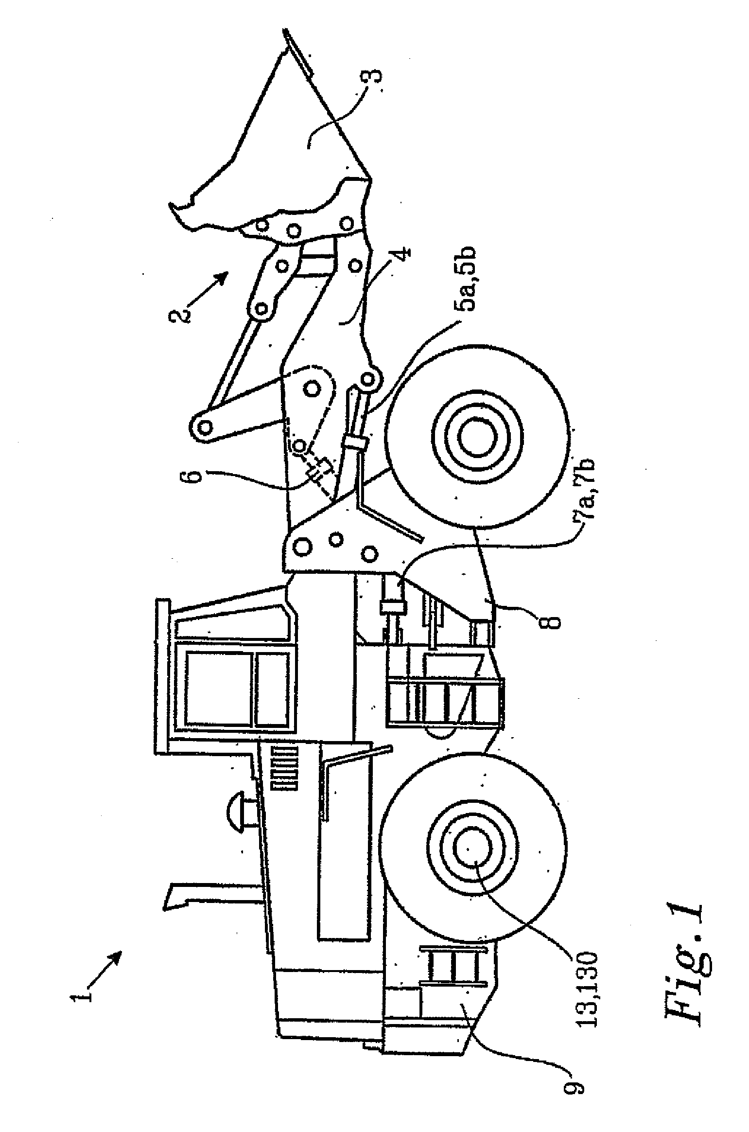
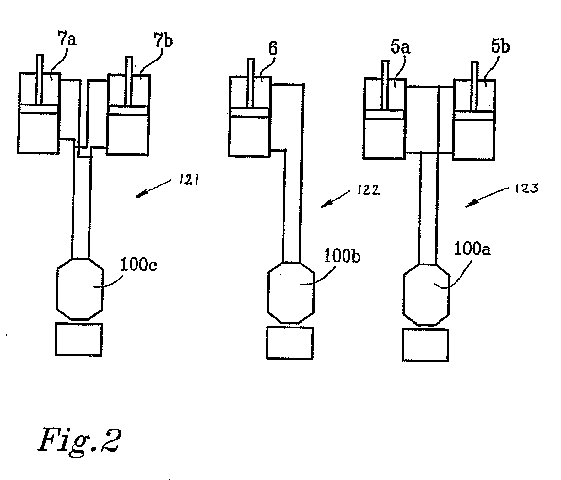
[0033]FIG. 1 is an illustration of a wheel loader 1 having an implement 2 in the form of a bucket 3. The bucket 3 is arranged on an arm unit 4 for lifting and lowering the bucket 3, and further the bucket 3 can be tilted or pivoted relative to the arm unit 4. The wheel loader 1 is provided with a hydraulic system comprising at least one hydraulic pump (not shown in FIG. 1) and working cylinders 5a, 5b, 6 for the operation of the arm unit 4 and the bucket 3. Furthermore, the hydraulic system comprises working cylinders 7a, 7b for turning the wheel loader by means of relative movement of a front body 8 and a rear body 9. A schematic illustration of such a hydraulic system is shown in FIG. 2.

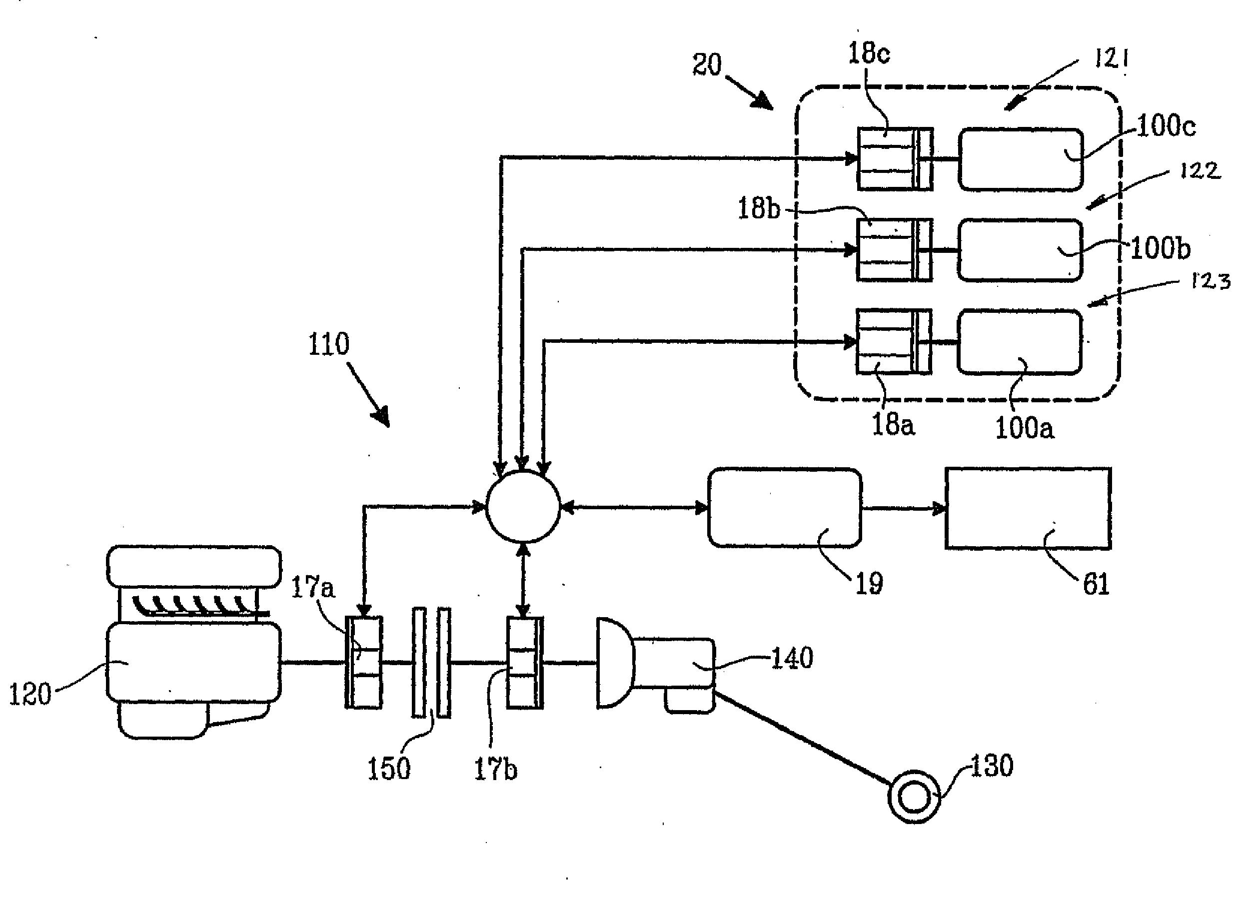
[0034]In the embodiment illustrated in FIG. 2, three hydraulic circuits 121,122,123 are disclosed. A first hydraulic circuit 121 is configured for a lifting function, a second hydraulic circuit 122 is configured for a tilting function and a third hydraulic circuit 123 is configured for a steering f...


PUM


Abstract

A working machine adapted for at least two functions, which include moving an implement and/or steering the machine, the machine includes: at least two hydraulic circuits, one hydraulic circuit for each of said functions, wherein each hydraulic circuit includes at least one hydraulic pump for operating the associated implement or steering function, a separate first electric machine drivingly connected to each of said hydraulic pumps for an individual supply of energy to the pump and extraction of energy from the pump, a transmission line for moving the working machine via driving wheels, wherein the transmission line includes at least one second electric machine, which is operatively connected to said first electric machines for an exchange of power between the hydraulic circuits and the transmission line.

Description

BACKGROUND AND SUMMARY[0001]The invention relates to a working machine adapted for at least two functions, which comprise moving an implement and / or steering the machine.The invention is applicable on working machines within the field of industrial construction machines, in particular wheel loaders. Although the invention will be described with respect to a wheel loader, the invention is not restricted to this particular vehicle, but may also be used in other heavy working machines, such as articulated haulers, trucks and excavators.[0002]A wheel loader is usually provided with an internal combustion engine, a transmission line, and a gearbox for supplying torque to the driving wheels of the wheel loader. The gearbox provides different gear ratios for varying the speed of the vehicle, and for changing between forward and backward driving direction. The transmission line comprises a hydrodynamic torque converter arranged between the internal combustion engine and the gearbox. The tor...

Claims


Application Information

Patent Timeline
IPC IPC(8): B60K1/02F16D31/00B60K1/04
CPCB60K6/387B60K6/442Y02T10/6234B60Y2200/415E02F9/20B60K6/547Y02T10/62E02F9/22F15B21/14
Inventor FILLA, RENOUNNEBACK, JOAKIMCARLSSON, SVEN-AKEERICSON, HANS
Owner VOLVO CONSTR EQUIP
Why Eureka
Try Eureka