
Method and apparatus for tidal power generation

Inactive Publication Date: 2009-08-27
THE BOEING CO
View PDF22 Cites 45 Cited by
  • Summary
  • Abstract
  • Description
  • Claims
  • Application Information

AI Technical Summary

Benefits of technology

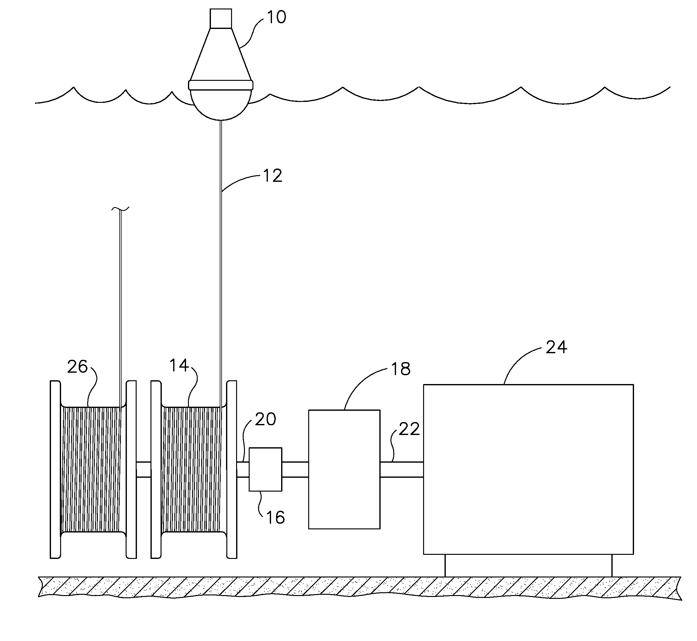
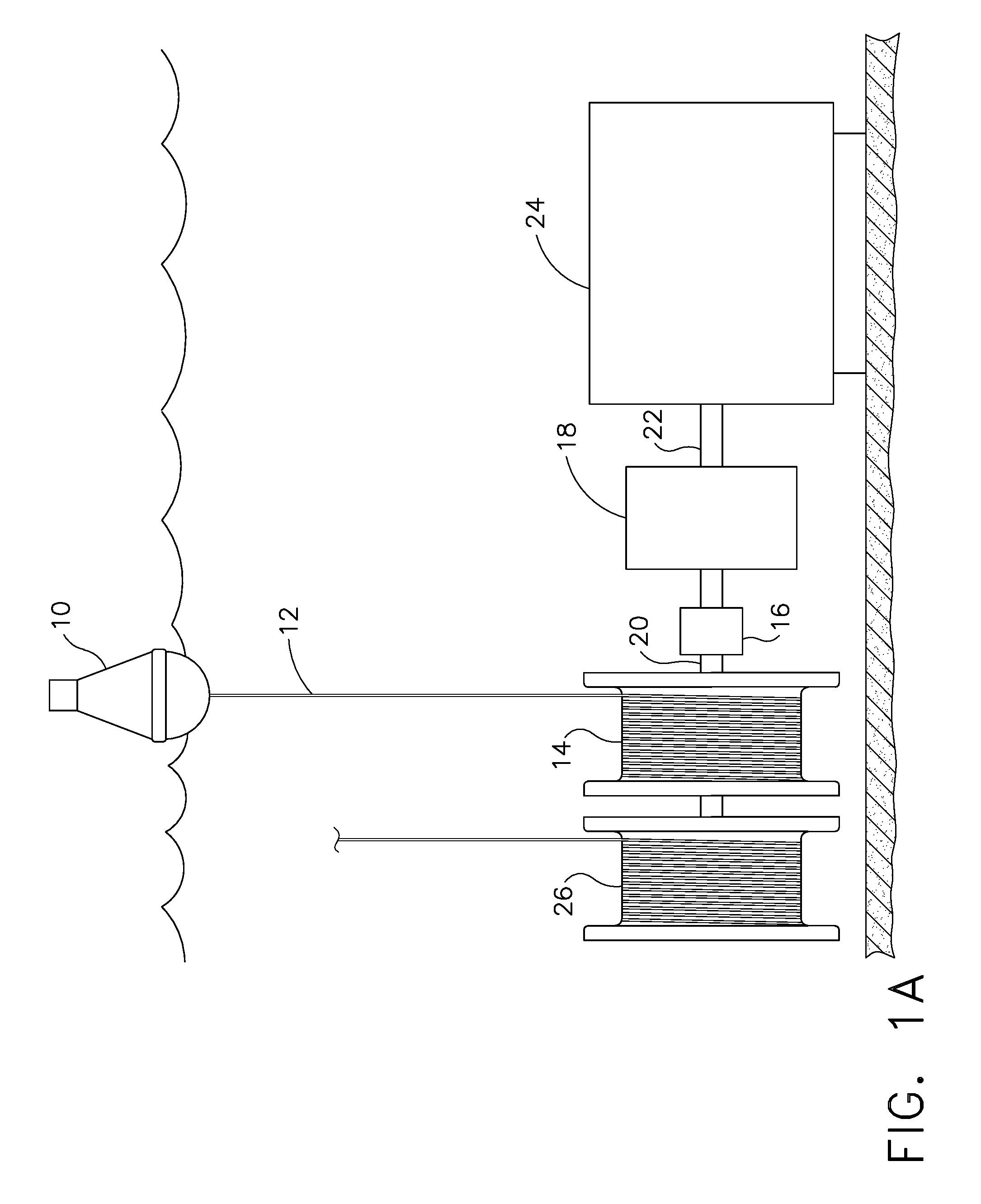
[0010]Exemplary embodiments of a tidal power generation system incorporate a buoy tethered to a first cable with a power generation spool engaging the first cable for rotational motion upon extraction of the cable by the buoy during elevation increases of the water on which the buoy is riding. An electrical generator is connected to the power generation spool and a rewinder for the power generation spool reels in the cable during receding water elevation. A gear drive interconnects the power generation spool and electrical generator with a gear reduction in certain embodiments for increasing generator rotational speed.
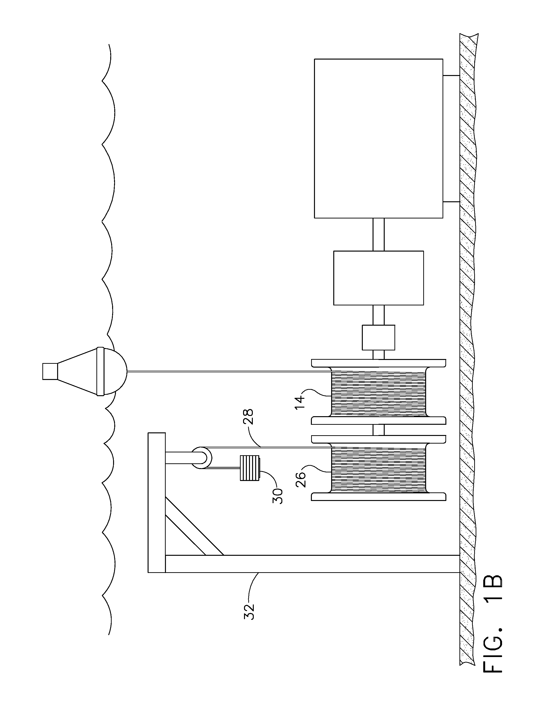
[0012]The embodiments provide a buoy riding on the ocean surface and connected to a first cable extractable from a first spool inducing rotation for energy collection. The first cable is extracted from the first spool using upward motion of the buoy during water level increases imparting rotational motion to a generator. Simultaneously a second spool coaxial with the first spool and engaged for common rotation rewinds a second cable attached to a mechanical energy storage system. Electrical energy created by the generator is transmitted to an electrical grid or stored. The second cable is extracted from the rewind spool using conversion of the energy stored in the mechanical energy storage system causing counter-rotational motion in both spools to rewind the first cable when receding water level lowers the buoy causing tension on the first cable to be reduced.

Problems solved by technology

The energy in moving that mass of water every day is absolutely enormous.
The potential negative effects of these devices is already known from what happens to fish that are expelled through existing systems in hydro-electric dams.
Use of these types of devices in the sea to capture the ocean current will produce the same negative effects.
This will result in injuries or deaths in marine life inhabiting the vicinity of such energy generation systems and may result in costly blade damage.
This creates an unsightly and large un-desirable structure that mars the scenic beauty of a coastline.

Method used


Image

  • Method and apparatus for tidal power generation
  • Method and apparatus for tidal power generation
  • Method and apparatus for tidal power generation

Examples


Embodiment Construction

[0020]The embodiment disclosed herein combines a simple floating mass such as a buoy with a generator to generate electricity through conversion of the energy required to raise the buoy during every wave or tidal cycle. In choppy waters a buoy is constantly bobbing up and down. This motion and the longer mode tidal rise are both energy sources that can be converted into electrical power. Currently buoys are secured to the ocean floor at a fixed point.

[0021]As shown in FIG. 1A a buoy 10 is secured with a cable 12 which may be substantially the same length as that necessary to allow the required motion of a conventionally moored buoy. The cable is attached to a first power generation spool 14 that is attached through a unidirectional bearing 16 to a gear drive 18. A first shaft 20 is connected intermediate the power generation spool and the unidirectional bearing and the gear drive engages an input shaft 22 for a generator 24. For an initial exemplary embodiment, a rewind spool 26 con...


PUM


Abstract

A tidal power generation system incorporates a buoy tethered to a first cable with a power generation spool engaging the first cable for rotational motion upon extraction of the cable by the buoy during elevation increases of the water on which the buoy is riding. An electrical generator is connected to the power generation spool and a rewinder for the power generation spool reels in the cable during receding water elevation. A gear drive interconnects the power generation spool and electrical generator with a gear reduction in certain embodiments for increasing generator rotational speed. The rewinder uses a rewind spool connected to the power generation spool and engaging a second cable for counter-rotational motion. A mechanical energy storage device is connected to the second cable. A suspended weight provides energy storage in the first embodiment while a spring attached to a fixed anchor point provides energy storage in an alternative embodiment.

Description

BACKGROUND OF THE INVENTION[0001]1. Field of the Invention[0002]Embodiments of the disclosure relate generally to the field of conversion of tide motion to electrical power and more particularly to a method and apparatus for employing rising tide forces exerted on a buoy extendibly tethered for rotational actuation of a gear drive connected to an electrical generator.[0003]2. Description of the Related Art[0004]There is a pressing need to develop clean energy sources. Since most of the surface of the earth is covered by water, water based systems provide the most potential for energy generation due to sheer volume. The gravitational effect that causes tides provides an enormous amount of energy since the mass and force of the water is many times greater than that of any air based system. Moving even just a few thousand cubic feet of water requires energy that would take up incredible amounts of airspace or physical land to be equaled with either wind or solar power. Therefore the ti...

Claims


Application Information

Patent Timeline
IPC IPC(8): F03B13/26
CPCF03B13/26Y02E10/28F03B13/264F03B13/262Y02E10/30Y02E10/20
Inventor JAUGILAS, JOHN M.
Owner THE BOEING CO
Learn More