

Speed Change Transmission Apparatus
- Summary
- Abstract
- Description
- Claims
- Application Information
AI Technical Summary
Benefits of technology
Problems solved by technology
Method used
Image


Examples
embodiment 1
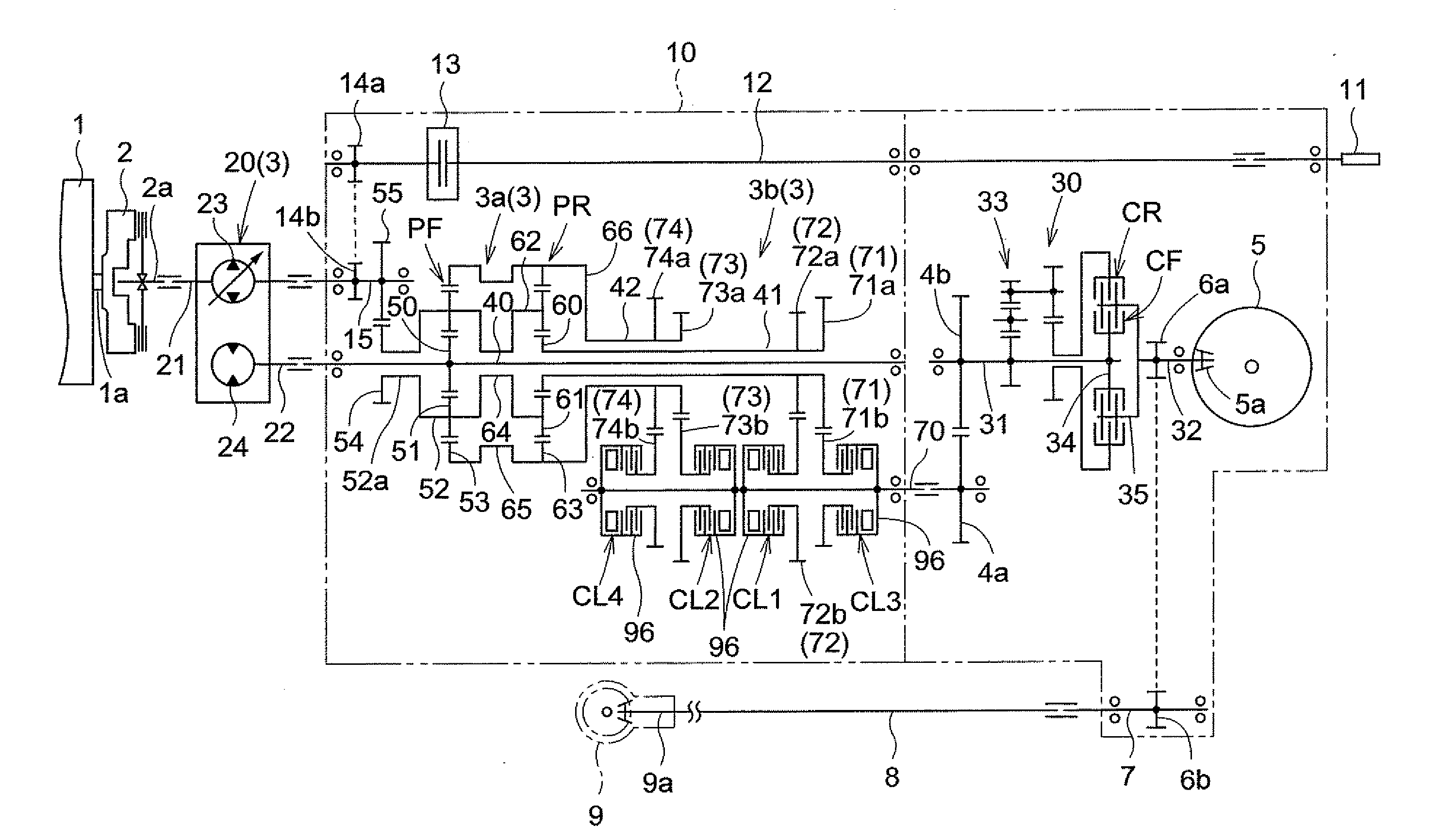
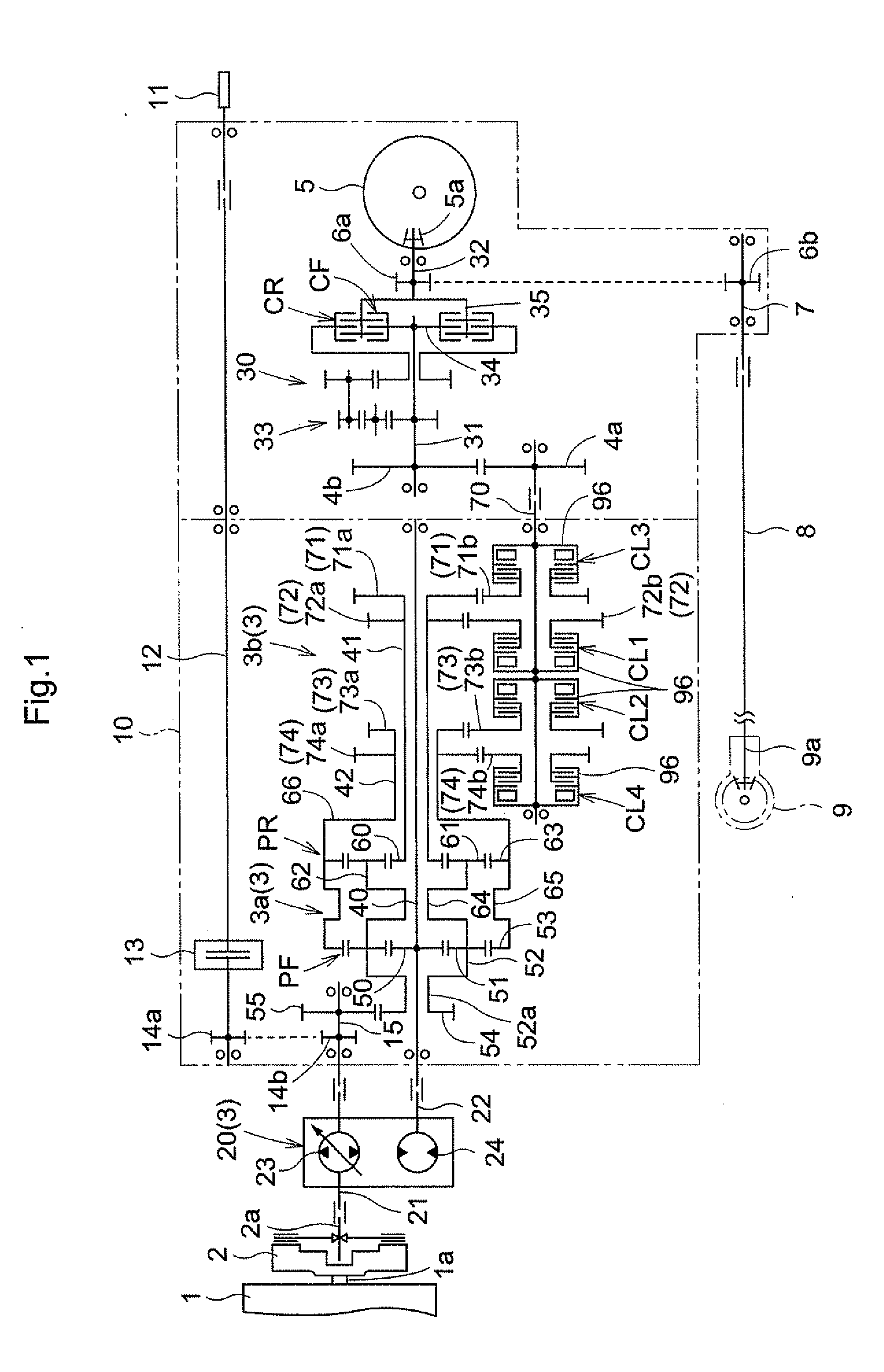
[0077]FIG. 1 is a diagram of a speed change transmission apparatus according to Embodiment 1. The speed change transmission apparatus according to Embodiment 1 is mounted in a traveling transmission apparatus included in a work vehicle such as a tractor.
[0078]The traveling transmission apparatus includes a main clutch 2 receiving output from an output shaft 1a of an engine 1, the speed change transmission apparatus 3 having an input shaft 21 operatively coupled to an output shaft 2a of the main clutch 2, a forward / reverse switchover device 30 having an input shaft 31 operatively coupled via transmission gears 4a, 4b to an output shaft 70 of the speed change transmission apparatus 3, a rear wheel differential mechanism 5 having an input gear 5a operatively coupled to an output shaft 32 of this forward / reverse switchover device 30, a front wheel output shaft 7 operatively coupled, via transmission gears 6a, 6b, to the output shaft 32 of the forward / reverse switchover device 30, and a ...
embodiment 2
[0110]FIG. 6 is a diagram showing a speed change transmission apparatus 103 according to Embodiment 2. Here, like members as those in Embodiment 1 are denoted with like reference marks or numerals and will not be explained in repetition basically. The speed change transmission apparatus 103 according to Embodiment 2 is mounted in a traveling transmission apparatus included in a tractor. This traveling transmission apparatus includes a main clutch 2 receiving output from an output shaft 1a of an engine 1, the speed change transmission apparatus 103 receiving output of the main clutch 2, a forward / reverse switchover device 30 operatively coupled to an output shaft 170 of this speed change transmission apparatus 103, a rear wheel differential mechanism 5 operatively coupled to an output shaft 32 of this forward / reverse switchover device 30 and a front wheel differential mechanism 9 operatively coupled to the output shaft 32 of the forward / reverse switchover device 30.
[0111]Comparing th...
embodiment 3
[0135]FIG. 10 is a diagram showing a speed change transmission apparatus 3 according to Embodiment 3. This traveling transmission apparatus includes a main clutch 2 receiving output from an output shaft 1a of an engine 1, the speed change transmission apparatus 3 receiving output of the main clutch 2, a forward / reverse switchover device 30 operatively coupled to an output shaft 70, as an output side rotational member, of this speed change transmission apparatus 3, a rear wheel differential mechanism 5 operatively coupled to an output shaft 32 of this forward / reverse switchover device 30 and a front wheel differential mechanism 9 operatively coupled to the output shaft 32 of the forward / reverse switchover device 30.
[0136]Comparing the traveling transmission apparatus mounting the speed change transmission apparatus 3 according to Embodiment 3 with the traveling transmission apparatus mounting the speed change transmission apparatus according to Embodiment 2, the traveling transmissio...
PUM
 Abstract
Description
Claims
Application Information