Friction stir welding machine and friction stir welding tool

a friction stir welding and welding tool technology, which is applied in the direction of manufacturing tools, soldering devices, auxillary welding devices, etc., can solve the problems of significant wear at the working site, thermal instability, and solid solution of tungsten, so as to prolong the life of welding tools, prevent degradation, damage and peeling of welding tools, and reduce the amount of materials to be welded

Active Publication Date: 2008-01-31
KAWASAKI HEAVY IND LTD
View PDF6 Cites 48 Cited by
  • Summary
  • Abstract
  • Description
  • Claims
  • Application Information

AI Technical Summary

Benefits of technology

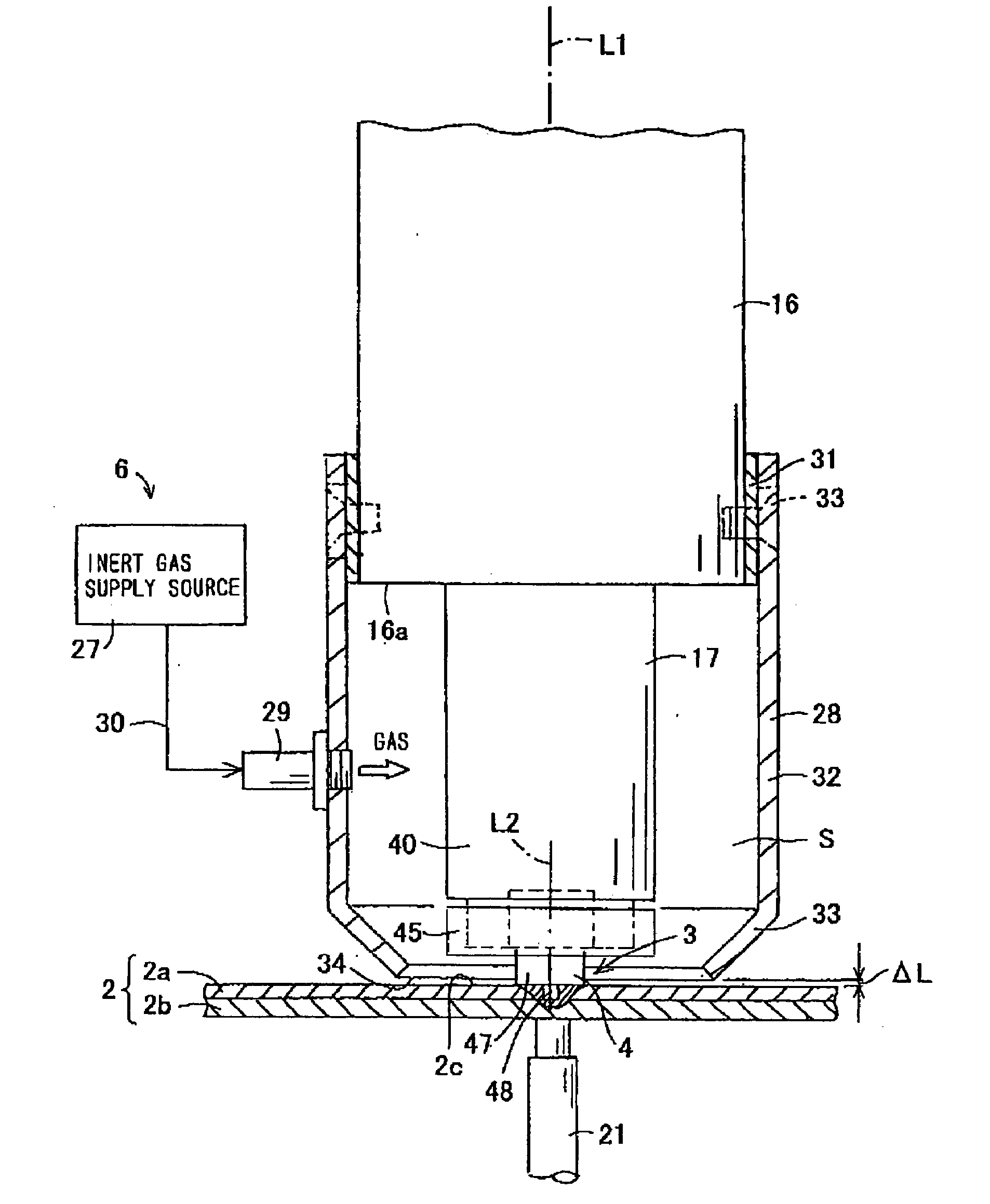
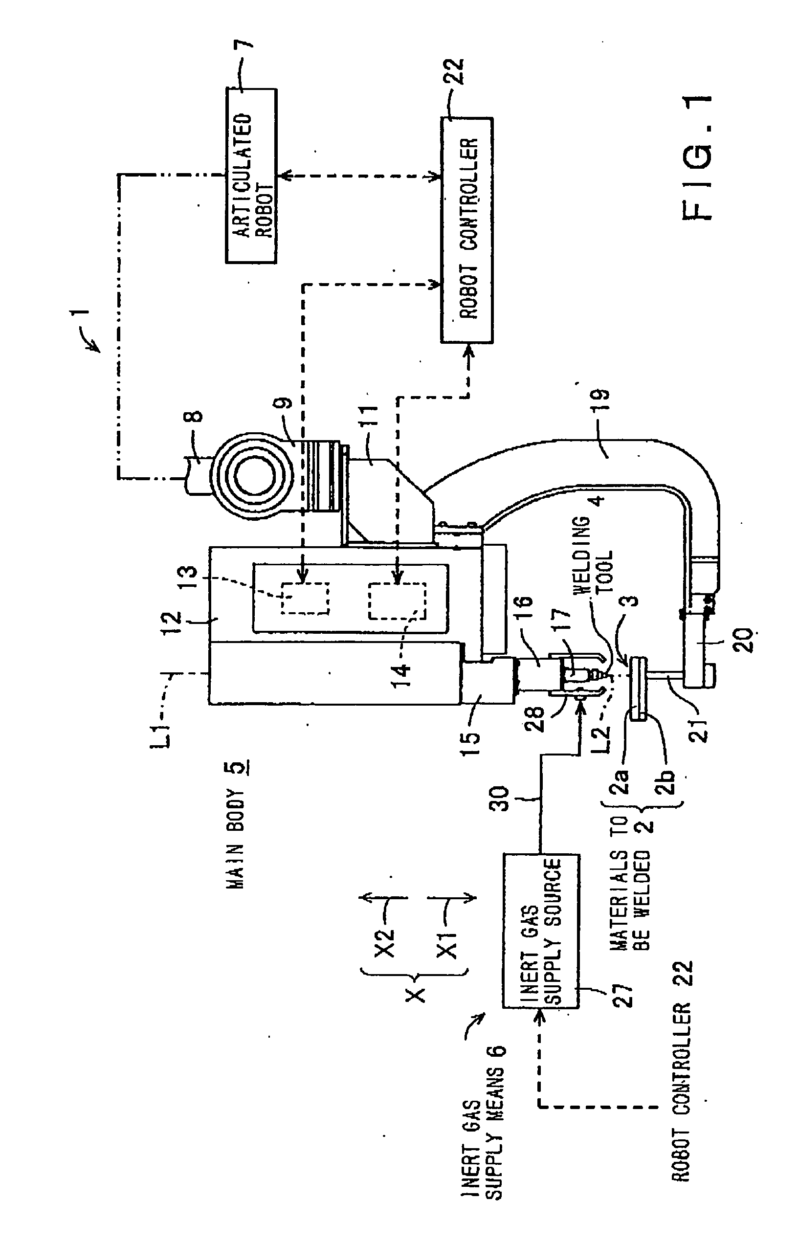
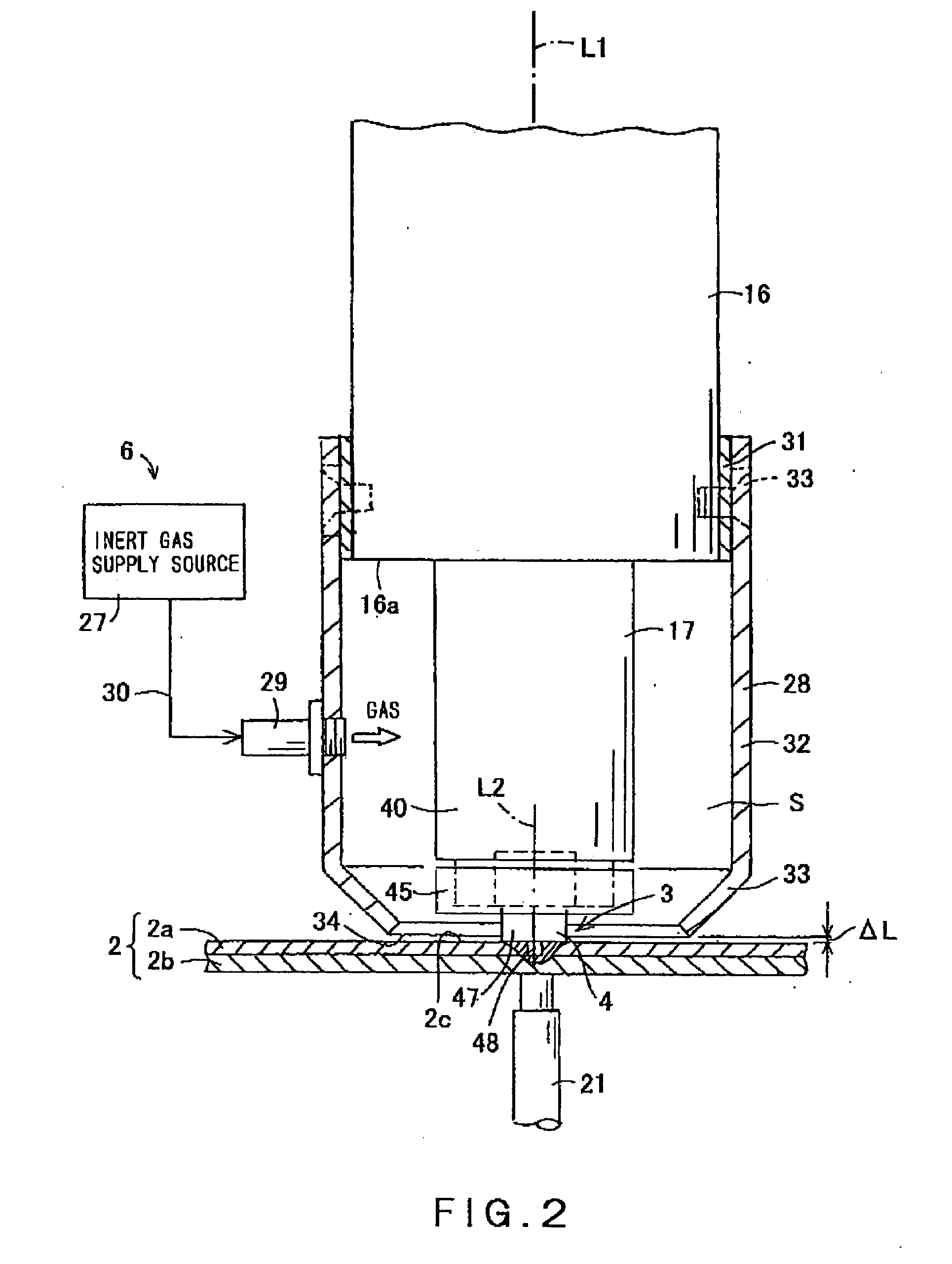
[0025]Since the coating of the welding tool is formed on at least a region to be in contact with the materials to be welded, and comprises aluminum nitride which has a low affinity to the materials to be welded, wear to be caused by chemical reaction between the materials to be welded and the welding tool can be prevented, thereby lengthening the life of welding tool.
[0026]The welding portion is blocked from the atmosphere by an inert gas supplied from the inert gas supply means, thus preventing degradation, damage and peeling of the welding tool due to oxidation of the coating.
[0027]Since the surface of the welding tool is covered with a coating comprising aluminum nitride, wear to be caused by chemical reaction of the welding tool with the materials to be welded can be prevented and the time required for welding the materials to be welded can be reduced by increasing the rotational speed of the welding tool, thereby enhancing efficiency of the welding work. By enabling a higher speed rotation of the welding tool, the amount of frictional heat to be generated by its contact with the materials to be welded can be increased, thus extending the region of the welding portion to be stirred, thereby enhancing the strength of welding between the materials to be welded. Since wear of the welding tool can be prevented due to the coating comprising aluminum nitride, solid solution to be caused by diffusion of constructional elements of the welding tool into the materials to be welded can be prevented, thereby preventing degradation of the strength of the welding portion of the materials to be welded.
[0028]According to the present invention, since a coating comprising aluminum nitride is formed on the surface of the welding tool, wear of the welding tool can be prevented, thus enhancing durability of the welding tool and lengthening the life of the welding tool. In addition, since the durability against wear of the coating of the welding tool can also be enhanced, the rotational speed of the welding tool can be increased, thereby to improve efficiency of the welding work. Furthermore, since the amount of heat to be generated by friction with the materials to be welded can be increased due to a higher rotational speed of the welding tool, the stirred region in the materials to be welded can be extended, thus improving the strength of welding at the welding portion of the materials to be welded. Moreover, by forming the coating comprising aluminum nitride on the surface of the welding tool, incorporation of detrimentally reactive elements of the welding tool into the welding portion, which may lead to degradation of the strength of welding, can be prevented.
[0029]Additionally, since the welding portion can be blocked from the atmosphere due to the inert gas, degradation, damage and peeling of the welding tool due to oxidation of the coating can also be prevented.

Problems solved by technology

Such a welding tool may tend to generate chemical decomposition of a material constituting the welding tool and / or diffusion of its constructional elements into the material to be welded due to heat generation caused by friction to the material to be welded, thus causing significant wearing at the working site, such as a shoulder portion or pin portion of the welding tool, which is to be used for generating driving force of stir by contacting with the materials to be welded.
Therefore, the material may tend to be decomposed under a higher temperature environment, thus being thermally unstable.
In addition, such a material is likely to cause solid solution of tungsten into the steel material.
Thus, wearing of the welding tool to be caused by such phenomena deteriorates the mechanical integrity of the region to be used for friction stir, leading to degradation of the strength of welding.
Furthermore, since the life of such an expensive welding tool is ended only by a slight use, there is also a problem from the economical view point.
However, wearing of the welding tool is accelerated.
Moreover, in view of the life of such an expensive welding tool, there is a significant limit to be considered in increasing the rotational speed.
Therefore, the reduction of the time required for welding and enhancement of the strength of welding are restricted in employing the aforementioned welding tool.
However, in the case where the material to be welded is a steel material, there is a problem similar to that in the related art in the Patent Document 1 described above.
However, also in this related art, when a steel material is used as the material to be welded, carbon which is a constructional element of the coating reacts chemically with the steel material, resulting in a similar problem as that described in each related art of the aforementioned Patent Documents 2, 3.

Method used


Image

  • Friction stir welding machine and friction stir welding tool
  • Friction stir welding machine and friction stir welding tool
  • Friction stir welding machine and friction stir welding tool

Examples


first embodiment

[0096]In the welding tool 104 of this embodiment, the mounting portion 46 is formed into a plate and has a generally elliptical section which is vertical to the axis L2. The fitting recess 43 in which the mounting portion 46 is to be fitted is formed into a space having a generally elliptical section which corresponds to the shape of the mounting portion 46, so that the mounting portion 46 can be loosely fitted therein. Thus, in the state where the mounting portion 46 is fitted in the fitting recess 43, angular displacement of the welding tool 104 about the axis L2 of the stirring rod 17 can be prevented. In addition, by arranging the fixing member 45 to make it abut one end face in the axial direction of the mounting portion 46 such that both end faces of the mounting portion 46 are interposed between the fixing member 45 and the stirring rod 17, displacement of the welding tool 104 in the axial direction can also be prevented, thus providing an effect similar to that of the weldin...

third embodiment

[0099]The fitting recess 32 of the stirring rod 17 of this third embodiment is formed into a shape in which the mounting portion 46 can be loosely fitted. The second shoulder portion 47B and second pin portion 48B are formed such that they can be received in the fitting recess 32, while the mounting portion 46 is fitted in the fitting recess 32 and the first shoulder portion 47A and first pin portion 48A project from the stirring rod 17. Namely, the fitting recess 32 is formed to include a fitting region in which the mounting portion 46 is to be fitted and a receiving region for receiving either one of the pairs of the shoulder portions 47 and pin portions 48.

[0100]By forming the receiving region to have a sectional shape smaller than that of the fitting region, when the welding tool 204 is fitted in the fitting recess 32, the portion of the welding tool 204 fitted therein will abut an end face of the mounting portion 46. In this state, both end faces of the mounting portion 46 are ...

fifth embodiment

[0108]FIG. 21 is a perspective view showing a welding tool 504 of still another embodiment according to the present invention. Also in the welding tool 504 of this embodiment, the shoulder portions 47A, 47B and the pin portions 48A, 48B are formed on each side of a mounting portion 524 as with the aforementioned welding tool 204 shown in FIG. 16. Namely, also in the case of employing the welding tool 504 of the fifth embodiment, the same effect as that of the welding tools 4, 204 described above can be obtained. It should be appreciated that the concavo-convex portions 400 of the mounting portion 524 may be formed in either one or both of end faces provided in the axial direction.

[0109]FIG. 22 is a bottom view showing a stirring rod 821 of yet another embodiment according to the present invention. The stirring rod821 includes a positioning projection or fitting portion as described above. The welding tool 622 is positioned coaxially with the stirring rod 721 such that it can be angu...


PUM

PropertyMeasurementUnit
diameteraaaaaaaaaa
diameteraaaaaaaaaa
thicknessaaaaaaaaaa

Abstract

The present invention is a friction stir welding machine adapted to perform solid phase welding on a welding portion of materials to be welded, by pressing a welding tool against the welding portion of the materials to be welded while rotating the welding tool, and forcing the welding tool to be advanced into a softened portion which is softened by a frictional heat while stirring the softened portion, wherein a coating made of aluminum nitride is formed on at least a region of the welding tool to be in contact with the materials to be welded.

Description

CROSS REFERENCE TO RELATED APPLICATIONS[0001]This application is based upon the prior Japanese Patent Application No. 2006-207214 filed on Jul. 28, 2006, the entire contents of which are incorporated herein by reference.BACKGROUND OF THE INVENTION[0002]1. Field of the Invention[0003]The present invention relates to a friction stir welding machine and a friction stir welding tool, which can be appropriately utilized for welding materials to be welded together, the materials comprising steel materials, such as steel materials to be used for general structures, those for constructional structures and those for steel plates.[0004]2. Description of the Related Art[0005]A typical example of the related art is described in Patent Document 1 listed below. This related art teaches a welding tool comprising a pin portion adapted to be in contact with a material to be welded is formed integrally on a central axis of a base material consisting of a heat resistive alloy, wherein lowering of hard...

Claims


Application Information

Patent Timeline
Patent Type & Authority Applications(United States)
IPC IPC(8): B23K20/12
CPCB23K20/1245B23K20/125Y10T408/9097B23K20/1265B23K2203/10B23K20/1255B23K2103/10
Inventor OHASHI, RYOJIFUJIMOTO, MITSUOKOGA, SHINJIKATO, ATSUSHI
Owner KAWASAKI HEAVY IND LTD
Why Eureka
Try Eureka