
Liquid dispensing system with temperature control

Inactive Publication Date: 2011-02-17
COOLTEK 2 GO
View PDF8 Cites 9 Cited by
  • Summary
  • Abstract
  • Description
  • Claims
  • Application Information

AI Technical Summary

Benefits of technology

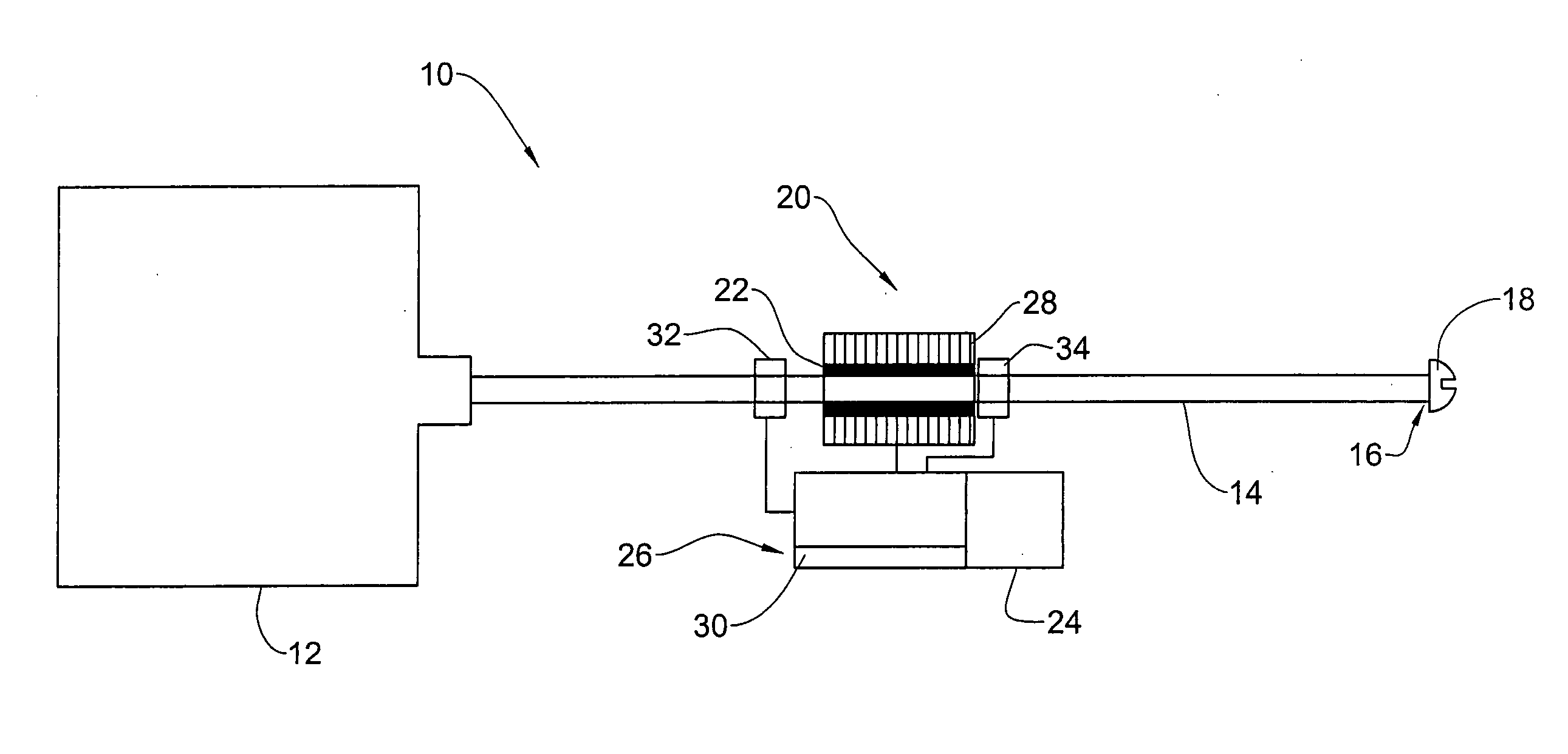
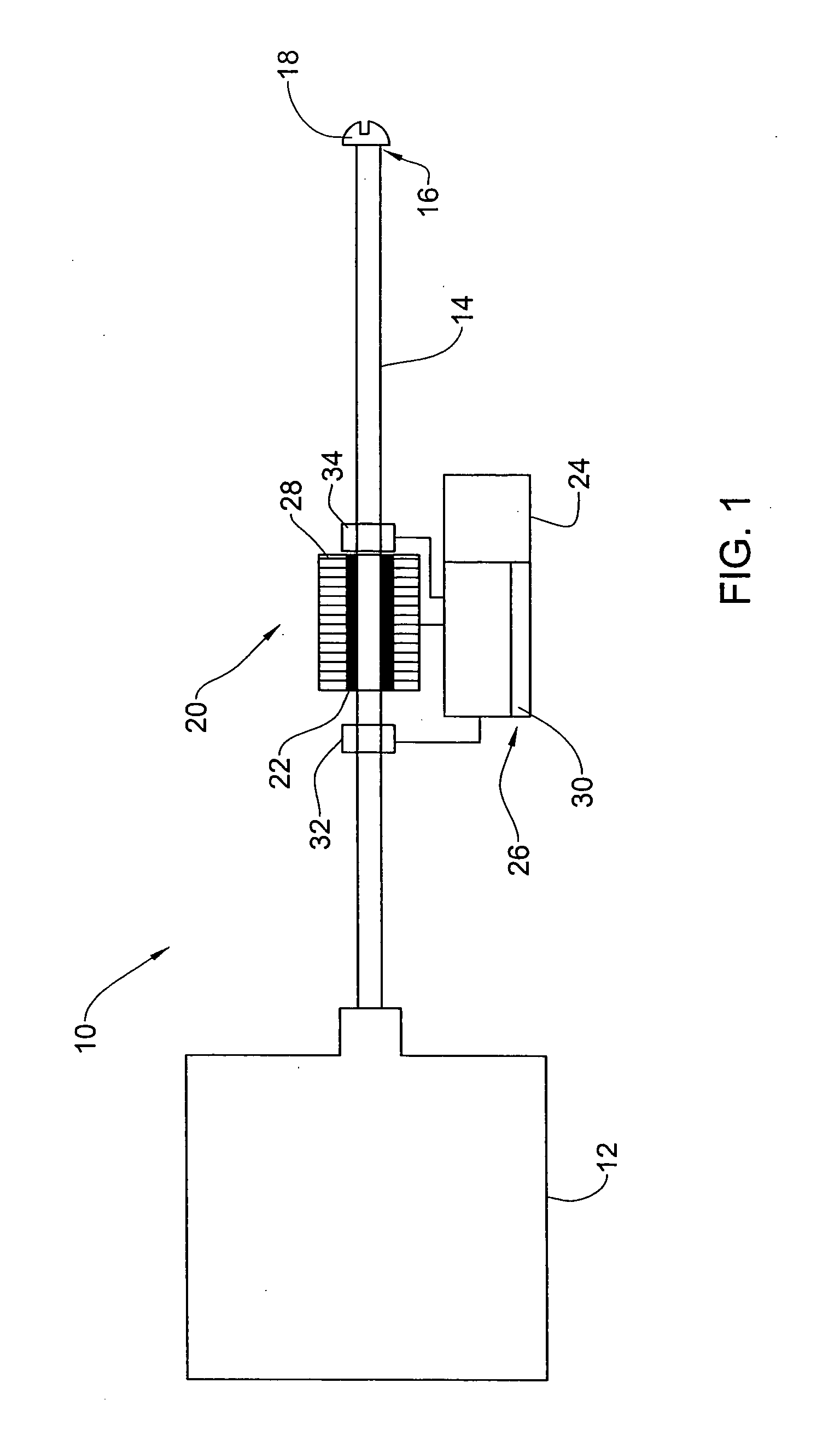
[0006]In accordance with the teaching herein, a new liquid dispensing system is provided which can be portable and is capable of providing liquid, particularly potable water, at a controlled temperature; for example, chilled liquids in a hot environment and warm liquids in a cold environment. One challenge overcome by the teaching herein is the provision of a temperature controlled liquid dispensing system with low power consumption. In accordance with the invention, this is achieved by activating a temperature control device disposed in a conduit system converting liquid from a reservoir to a liquid dispensing outlet, only upon sensing a demand for it (by the user).
[0012]The principle of activating the control module only upon demand, while controlling the temperature of only the liquid that flows out of the reservoir through the conduit system and out through the dispensing outlet, may save power required for the temperature control module operation as compared to liquid dispensing systems (including portable liquid dispensing systems) that operate in a batch mode to heat or cool a liquid contained in a temperature controlled liquid reservoir. A system in accordance with the teaching herein may thus perform effectively with a relatively small power source, e.g. a battery. The battery may be rechargeable or non-rechargeable (i.e. replaceable). The power source may be rechargeable either by some embodiments of the present disclosure, by solar panels, a motion-induced generator, or a spring generator etc. The battery may be connected to a capacitor to allow on demand discharge of power.

Problems solved by technology

One challenge overcome by the teaching herein is the provision of a temperature controlled liquid dispensing system with low power consumption.

Method used


Image

  • Liquid dispensing system with temperature control
  • Liquid dispensing system with temperature control
  • Liquid dispensing system with temperature control

Examples


Embodiment Construction

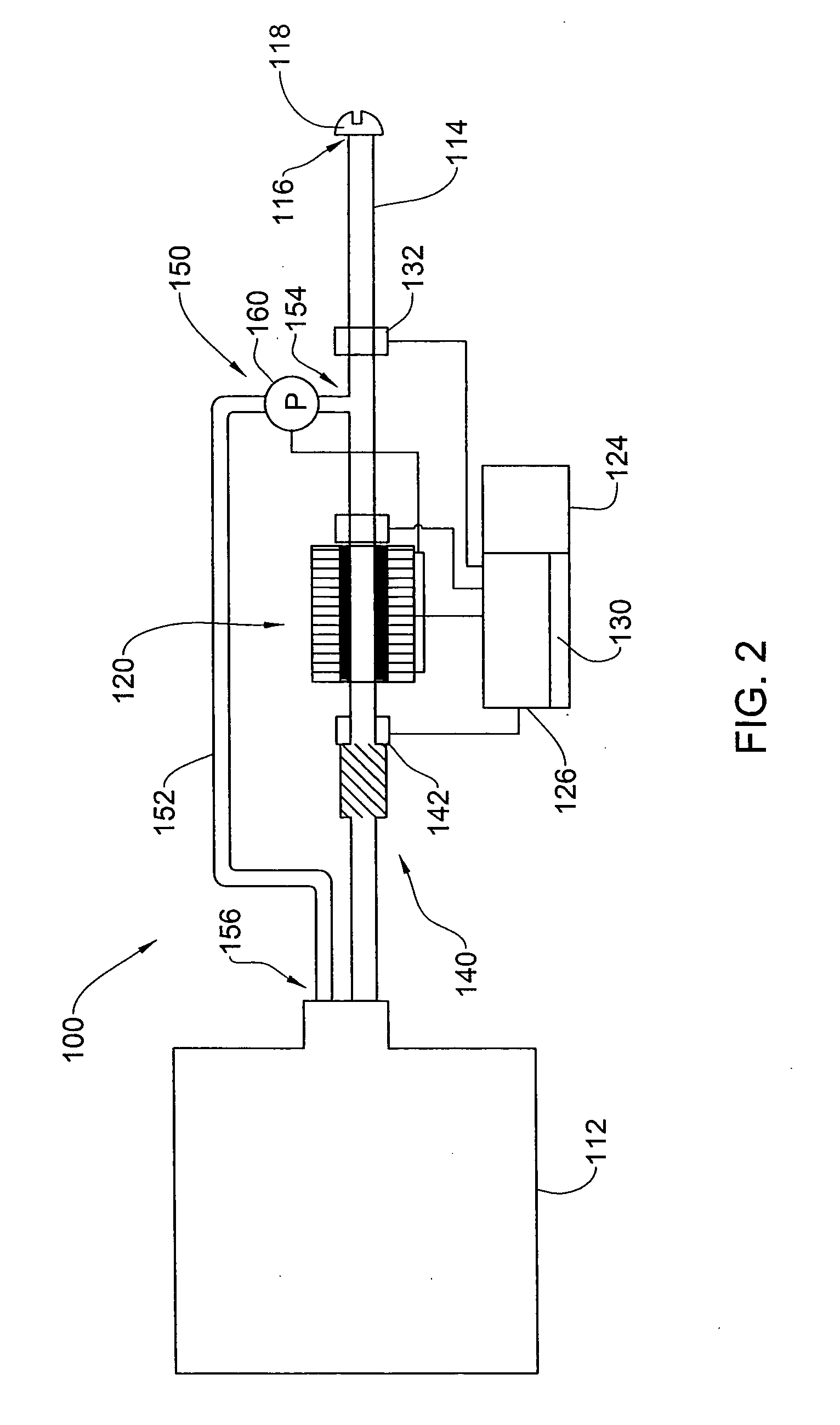
[0022]Reference is made to FIG. 1 which provides a schematic illustration of an on demand liquid cooling / heating system 10, comprising a liquid reservoir 12, which may be a bottle, a bag, a canteen, a pouch or any other container for holding therein liquid to be used by the user. The reservoir may be fitted into a back pack or any other carrying arrangement, e.g. using a fast connection arrangement. The liquid reservoir 12 is connected to a conduit system 14, comprising a tube with a first end thereof connected to reservoir 12 and a second end thereof with an outlet 16 for dispensing liquid to the user. The liquid conduit system 14 establishes flow communication of liquid between the reservoir 12 and liquid outlet 16. The liquid outlet 16 may be equipped with a dispensing mouthpiece and a valve 18, preferably a one way valve to prevent reverse flow.

[0023]While a single tube is illustrated in FIG. 1, it is noted that conduit system 14 may comprise a combination of individual number o...


PUM

PropertyMeasurementUnit
Temperatureaaaaaaaaaa
Poweraaaaaaaaaa

Abstract

The present invention provides an on-demand liquid cooling / heating system, comprising: a liquid outlet for dispensing liquid to a user; a conduit system for flow communication between a liquid reservoir and the liquid outlet; a temperature control device disposed in the conduit system for controlling the temperature of liquid flowing therethrough, and comprising a thermoelectric temperature control device linked to an electric power source and to a control module for controlling the operation of the temperature control device; and a sensor for sensing liquid demand and for activating the temperature control module upon sensing a demand.

Description

FIELD OF THE INVENTION[0001]This invention relates to a liquid dispensing system with a temperature control device for cooling or heating, of the dispensed liquid.BACKGROUND OF THE INVENTION[0002]Outdoors activities require portable hydration solutions for the replenishment of water lost through sweating and for quenching of thirst. The old traditional canteens have evolved to plastic liquid bottles and further into backpack pouches equipped with a hose which has a mouthpiece at its end, commonly known as “camelbaks”. The camelbacks are comfortable, can hold a relatively large volume of liquid and free the user from the need to hold a bottle, thus allowing him to drink in a more or less continuous manner.[0003]It is often more desirable to have the liquid at a higher or lower than ambient temperature, depending on the circumstances. On a warm day it is preferable to consume a chilled drink. On a cold day, while skiing for example, it may be desirable to consume a warm drink. Further...

Claims


Application Information

Patent Timeline
IPC IPC(8): B67D7/80
CPCA45F3/20A45F2003/163F25D2331/811F25B21/04F25D31/002A45F2003/166
Inventor HILLEL, RAMSHAAF, DANIELSHALVI, RAMAVNI, JOED
Owner COOLTEK 2 GO
Learn More