Apparatus and method for resistivity well logging

a resistivity well and apparatus technology, applied in the field of electric logging, can solve the problems of not being able to solve the mathematically impossible three desired unknowns (rt, rxo, di) from only two measurements, the vertical response of the attenuation measurement is not as sharp as the vertical response of the phase difference measurement, and the separation of phase difference and attenuation curves

Inactive Publication Date: 2004-05-13
ULTIMA LABS
View PDF9 Cites 114 Cited by
  • Summary
  • Abstract
  • Description
  • Claims
  • Application Information

AI Technical Summary

Problems solved by technology

Separation of the curves is used to identify invasion; however, it is mathematically impossible to solve for the three desired unknowns (Rt, Rxo, Di) from only two measurements.
Another disadvantage of the earlier generation tools is that the vertical response of the attenuation measurement is not as sharp as the vertical response of the phase difference measurement.
Also, it is known in the art that dielectric uncertainty can cause the phase difference and attenuation curves to separate even when no fluid invasion is present.
Another disadvantage of the attenuation measurement is reduced dynamic range when compared to the phase difference measurement.
The limited dynamic range of the attenuation measurement sets an upper resistivity limit on the utility of apparatus employing this method for detecting invasion.
However, these prior art apparatus and method still have various limitations.
The additional transmitters and receivers, it will be appreciated, added greatly to cost and complexity of the tools.
However, this group of tools still required multiple additional transmitters and receivers, each tuned to transmit or receive only a single frequency.
Again, increased cost and complexity of tools resulted.
Many of these prior art apparatus exhibit other limitations, such as high electrical power consumption.
Detecting multiple frequencies simultaneously results in the shortest possible measurement time.

Method used


Image

  • Apparatus and method for resistivity well logging
  • Apparatus and method for resistivity well logging
  • Apparatus and method for resistivity well logging

Examples


Embodiment Construction

[0042] Overview of MWD system

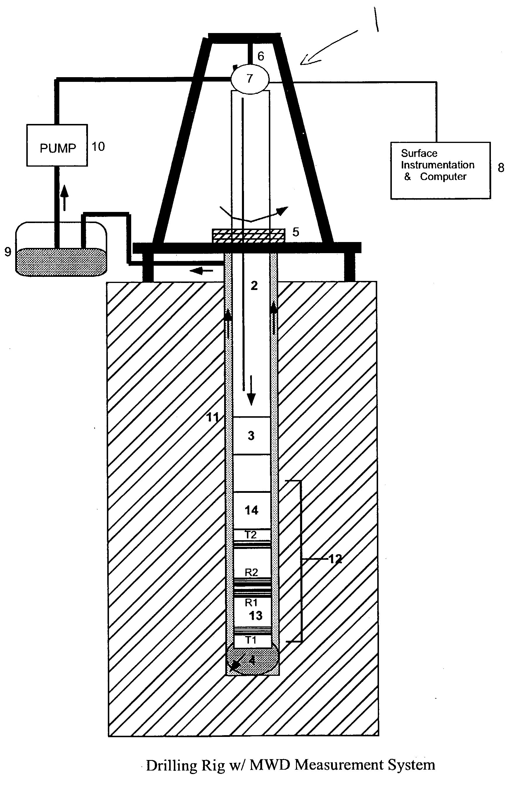
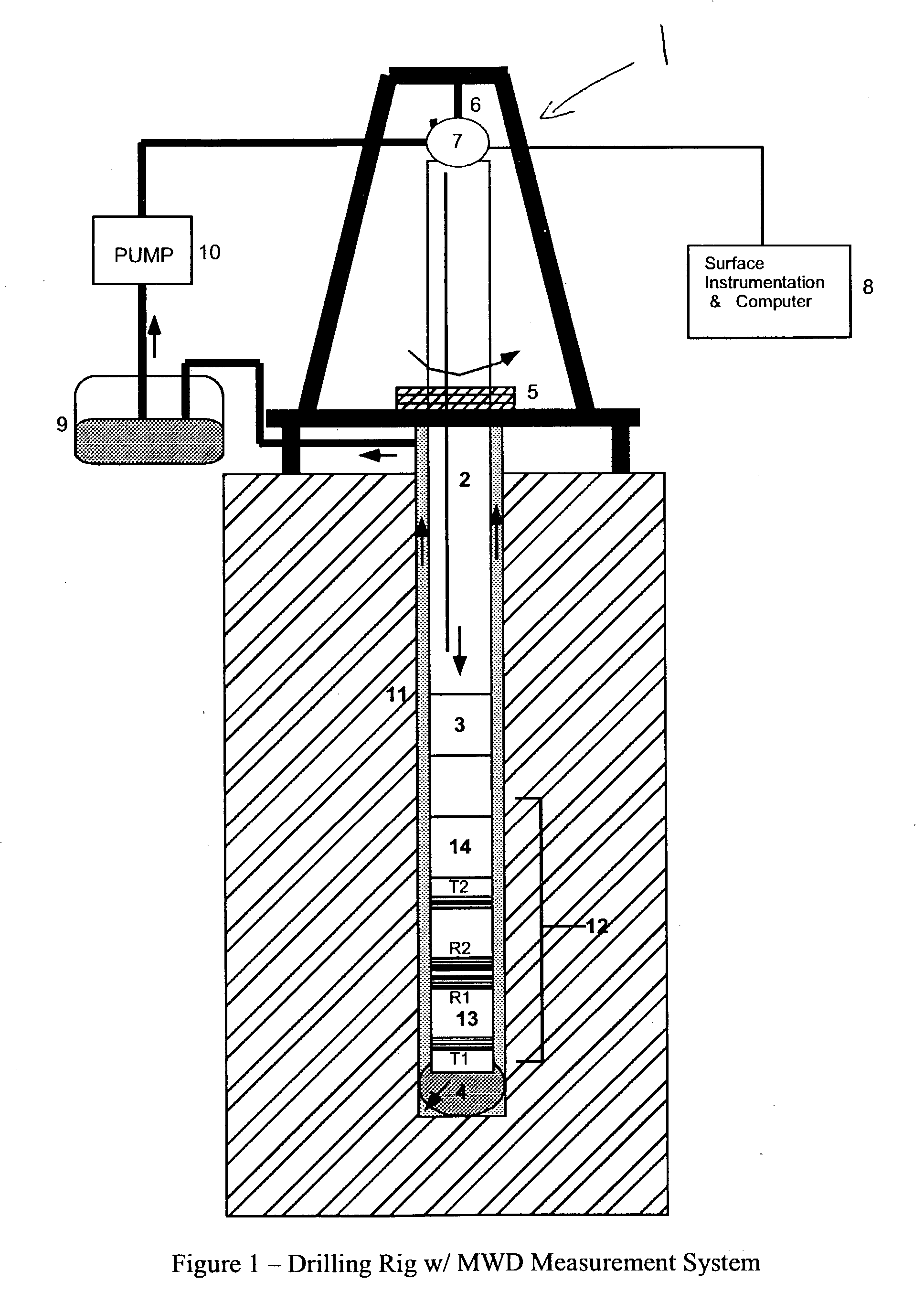
[0043] FIG. 1 illustrates an embodiment of the invention in the form of an MWD or logging-while-drilling apparatus and method. A drilling rig (1) is located over a borehole formed in the earth by rotary drilling. A drill string is suspended within the borehole and typically includes drill pipe from the surface (2), one or more drill collars (3), a mud motor (optionally), and a drill bit (4) at its lower end. During rotary drilling, the drill string and drill bit attached thereto are rotated by a rotating table (5), which engages a kelly at the upper end of the drill string. The drill string is suspended from a hook (6) attached to a traveling block (not shown). The kelly is connected to the hook through a rotary swivel (7) which permits rotation of the drill string relative to the hook. Sensors and associated instrumentation (8) monitor movement and load of the hook and / or kelly in order to generate a record of depth of the drill bit vs. time. This instr...


PUM


Abstract

Well logging apparatus and methods for determining formation resistivity at multiple (>3) depths of investigation. At least one transmitter antenna and at least two receiver antennas are mounted in a logging tool housing, on substantially a common axis. The antennas are untuned coils of wire. Electromagnetic energy is emitted at multiple frequencies from the transmitter into the formation. The receiver antennas, which are spaced apart from each other and from the transmitter, detect reflected electromagnetic energy. Formation resistivity at multiple depths of investigation is determined using only phase differences in the reflected energy at the different frequencies, minimizing false indications of invasion due to mismatch of vertical response with attenuation measurements and also permitting correcting for the effects of varying dielectric constant of the formation. The apparatus minimizes the number of antennas, electronics complexity, required power, and measurement time required to determine resistivity at multiple depths of investigation.

Description

[0001] 1. Field of the Invention[0002] This invention relates to the field of electric logging of "wells" or earthen boreholes. In particular, the invention relates to well logging apparatus and methods for determining formation properties, such as resistivity, at several different distances extending radially from the borehole into the surrounding formation. The invention has general applications in the well logging art, but is particularly useful in measurement while drilling ("MWD") applications.[0003] 2. Description of the Related Art[0004] Resistivity logging is a commonly used technique for evaluating potential hydrocarbon-bearing formations surrounding a borehole drilled into the earth. Porous formations are more resistive to a flow of electric current when they are saturated with hydrocarbons, and less resistive when saturated with water (which contains some amount of salt, rendering it more or less conductive). The formation immediately surrounding the borehole can be alter...

Claims


Application Information

Patent Timeline
Patent Type & Authority Applications(United States)
IPC IPC(8): G01V3/30
CPCG01V3/30
Inventor MACUNE, DON T.
Owner ULTIMA LABS
Why Eureka
Try Eureka