Eureka AIR delivers breakthrough ideas for toughest innovation challenges, trusted by R&D personnel around the world.

Energy dispersion device

a technology of energy dispersion device and energy dispersion beam, which is applied in the direction of radiation measurement, optical radiation measurement, spectral modifier, etc., to achieve the effect of large pixel count, high pixel count and greater dynamic rang

Active Publication Date: 2014-11-11
SPECTROCLICK
View PDF6 Cites 45 Cited by
  • Summary
  • Abstract
  • Description
  • Claims
  • Application Information

AI Technical Summary

Benefits of technology

[0003]The invention provides an energy dispersion device and method of use by which a member of the general public can evaluate the physical and chemical composition of matter on site without the need for specialize training or expensive equipment. The invention is based on the discovery of an arrangement of optical components based upon which an energy dispersion device or a spectrograph such as a spectrometer, spectrophotometer, or spectrofluorimeter can be constructed. The arrangement of optical components can be used to generate a spectrum having multiple spectral orders from which meaningful measurements and conclusions can be obtained. This arrangement allows for real time calibration and, thus, lessens the need for costly instrument components such as optical benches, lenses and mirrors that have matched coefficient of thermal expansion to maintain wavelength calibration that would be necessary to obtain useful data. In addition, the gaps between orders can be used to precisely measure stray light allowing for modeling and compensation. Changes in stray light levels may be interpreted to indicate levels of particulate matter suspended in solution (a measurement commonly known as nephalometry). The arrangement of optical components provided by the invention can compensate for the limited dynamic range of certain detectors, especially imaging detectors. The energy dispersion device of the invention can be used with a high pixel count electronic array detector of arbitrary dynamic range and arbitrarily large pixel count. The energy dispersion device can have a dynamic range that is greater than the dynamic range of the detector due to the unique arrangement of the optical components. The invention provides a more cost effective analytical instrument that is also easy to use and therefore amenable to widespread adoption.
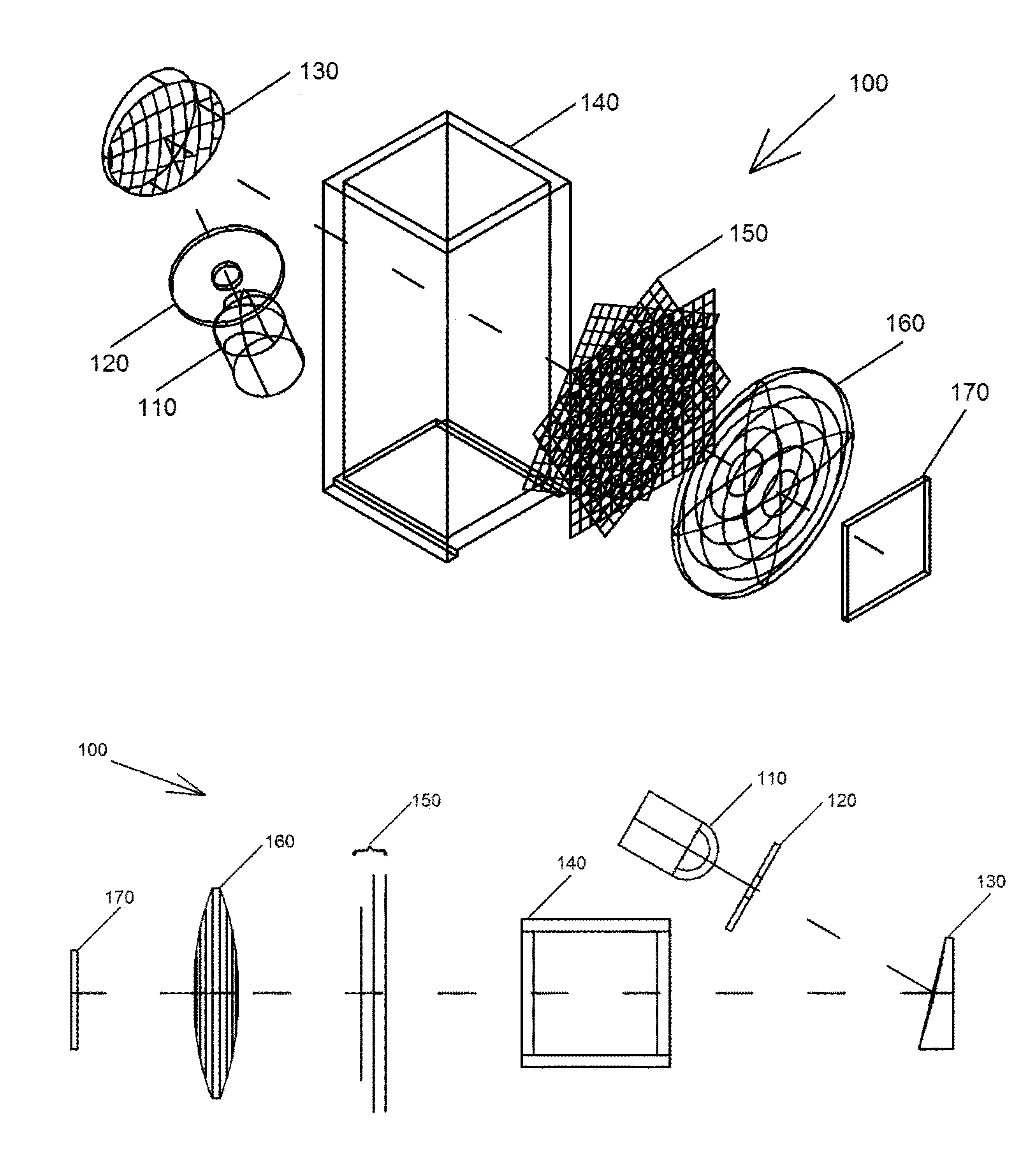
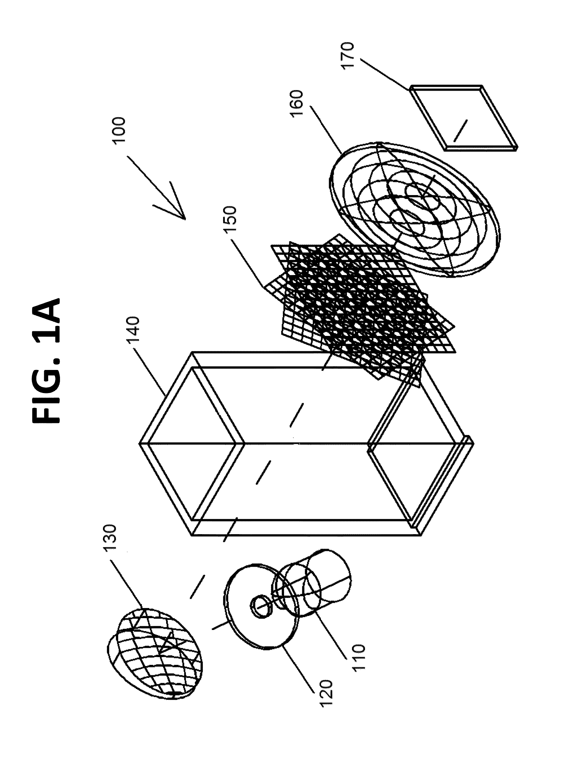
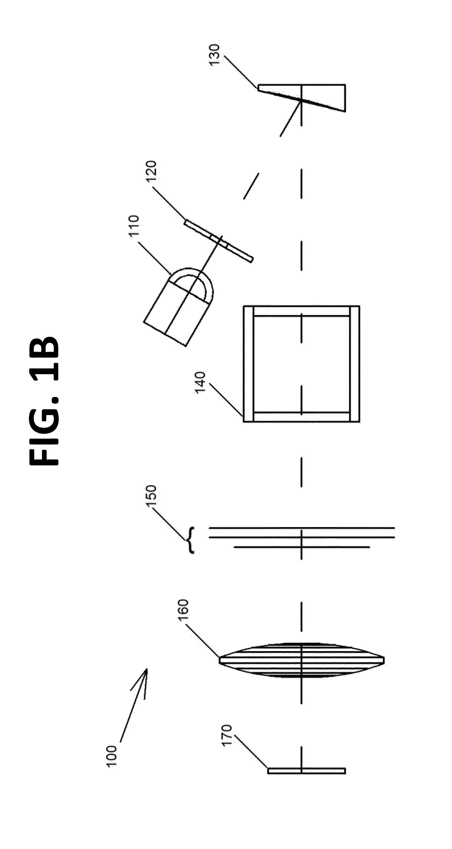
[0017]In another embodiment, the invention provides a spectrograph that includes (1) a light source such as a light-emitting diode (LED), an arc lamp, or laser, (2) a collimating mirror such as an off-axis parabola, (3) a jig to hold in appropriate alignment a cuvette. Into this holder is placed a cuvette to which is bonded, onto which is printed, or otherwise to which is attached a stack of diffraction gratings mutually rotated so as to generate a multiplicity of diffraction orders from collimated light. The grating-covered face of the cuvette is so positioned as to be facing away from the parabolic mirror and towards any detector array. The cuvette is positioned so that the collimated light from the parabolic mirror enters a clear face of the cuvette and exits a clear face on the outside of which is the bonded grating stack. As illustrated in FIGS. 9A through 9C, the cuvette may be of the common type widely used in spectrophotometers, or may be modified with handling tabs to make it easier for a user to avoid touching the faces of the cuvette and to assist in so designing the holding jig to assist in orienting the cuvette correctly. The multiplicity of orders and the stray light between the orders is focused onto a detector using a suitable lens or mirror. The detector and suitable lens or mirror may or may not be mounted on the spectrograph. The lens might be associated with a camera, either integral to the camera or a demountable lens. The light is detected by an array detector such as a charge-coupled array or charge-coupled device (CCD), complementary metal oxide on silicon array (CMOS array), or charge-injection array (CID).
[0019]Dispersion devices have been patented by D. Brady et al. that use a large opening instead of a narrow slit to admit light to an energy-dispersing device such as a filter, grating, or prism. Light then falls on a Hadamard mask, a programmable, binary shutter allowing passage of selected combinations of wavelengths onto, e.g., a charge-coupled array detector. Although the throughput of these devices is higher than for similar resolution grating spectrographs of conventional design, and the Multiplex or Jacquinot Advantage of these devices allow for improved precision and throughput compared to conventional designs, unlike the invention, the dynamic range of measurement in the Brady dispersion device is similarly restricted because the dynamic range of the detector.

Problems solved by technology

Instruments that can provide a direct and immediate benefit to the general public, however, such as those for measuring water quality, the presence of contamination in food, presence of common infectious bacteria, soil composition, or the identity of questionable substances remain uncommon and used only by those with specialized training—due, in part, to cost and ease of use.

Method used


Image

  • Energy dispersion device
  • Energy dispersion device
  • Energy dispersion device

Examples


example

[0095]A spectrophotometer was constructed using, as a light source, a white LED (RL-5-W5020), which produces a continuous spectrum from 420 to 720 nm, with peak emission from the blue, primary source LED near 450 nm (the LED is manufactured with an overcoat containing yttrium aluminum oxide phosphor which generated light over the remainder of the visible spectrum). The LED was powered by a lithium ion battery (CR2032). The LED back-illuminated a 50 micrometer diameter pinhole in a thin metallic disk, positioned one focal length from a 30° off-axis paraboloidal reflector (Edmund Scientific NT63-180). In addition, a plastic spectrophotometry cuvette and two-dimensional, holographic transmission gratings (Rainbow Symphony Store #01602 gratings with parallel lines 500 per mm) were used. In the experiment, three of these double-dispersion diffraction gratings (gratings in which the patterning is two-dimensional so that dispersion is in both vertical and horizontal directions) were stacke...


PUM

PropertyMeasurementUnit
angleaaaaaaaaaa
angleaaaaaaaaaa
angleaaaaaaaaaa

Abstract

The invention provides an energy dispersion device, spectrograph and method that can be used to evaluate the composition of matter on site without the need for specialized training or expensive equipment. The energy dispersion device or spectrograph can be used with a digital camera or cell phone. A device of the invention includes a stack of single- or double-dispersion diffraction gratings that are rotated about their normal giving rise to a multiplicity of diffraction orders from which meaningful measurements and determinations can be made with respect to the qualitative or quantitative characteristics of matter.

Description

CROSS-REFERENCE TO RELATED APPLICATIONS[0001]The present application claims the benefit of U.S. Provisional Patent Application No. 61 / 546,216, filed Oct. 12, 2011, and U.S. Provisional Patent Application No. 61 / 570,049, filed Dec. 13, 2011, both of which are hereby incorporated by reference in their entireties.BACKGROUND OF THE INVENTION[0002]Many analytical instruments use the intensity of light of various colors over a range of wavelengths to study the composition of matter, both qualitative and quantitative. When light interacts with matter, it may undergo many processes including but not limited to absorption, scattering, reflection, refraction, fluorescence, and phosphorescence. Instruments are now available to measure the extent of these processes with good precision and accuracy throughout the ultraviolet, visible, near-infrared, infrared, and other regions of the electromagnetic spectrum. It is generally true that the closer a measurement is made to the information source mo...

Claims


Application Information

Patent Timeline
Patent Type & Authority Patents(United States)
IPC IPC(8): G01J3/28G01J3/42G01J3/44G01J3/18G02B27/44G01K13/00G01J3/10
CPCG01J3/1804G01J3/4406G02B27/44G01K13/00G01J3/28G01J3/10G01J3/42G02B27/4272G02B27/4244
Inventor SCHEELINE, ALEXANDERBUI, THU ANH
Owner SPECTROCLICK
Why Eureka
Eureka Blog
Learn More