Method of signaling allocated resources

a signaling resource and resource allocation technology, applied in the field of wireless communication systems, can solve the problems of increasing signaling overhead, reducing the overall signaling overhead associated with scheduling re-transmissions, and spreading reverse link transmission over a narrow bandwidth and not spreading, etc.

Inactive Publication Date: 2012-09-18
ALCATEL LUCENT SAS
View PDF7 Cites 71 Cited by
  • Summary
  • Abstract
  • Description
  • Claims
  • Application Information

AI Technical Summary

Benefits of technology

[0008]An embodiment of the present invention is a method of signaling hopping locations selected by a scheduling entity using a frequency hopping pattern indicator for indicating hopping locations for at least two re-transmissions. The frequency hopping pattern is selected by the scheduling entity which, in one embodiment, has knowledge of all or at least a plurality of scheduled reverse link transmissions or restrictions upon reverse link transmissions, thereby allowing reverse link re-transmissions to be scheduled in a manner compatible with other reverse link transmissions and restrictions. Overall signaling overhead associated with scheduling re-transmissions is reduced through the signaling of a single message which indicates hopping locations for at least two re-transmissions instead of two or more separate messages, wherein each of the two or more separate message indicates a hopping location for an individual re-transmission.

Problems solved by technology

A drawback with localized sub-carrier allocation is that the reverse link transmission is spread over a narrow bandwidth and not spread over a wide bandwidth.
Spreading the reverse link transmission over a narrow bandwidth does not allow the reverse link transmission to experience much, if any, frequency diversity.
Signaling the hopping locations each time a re-transmission is necessary increases signaling overhead, which is undesirable because it reduces system capacity.
However, in this implementation, the scheduler does not have control of all scheduling decisions.
Scheduling decisions with respect to reverse link re-transmissions are made by the mobile stations and may be incompatible with restrictions and / or scheduling decisions made by the scheduler or other mobile stations.

Method used


Image

  • Method of signaling allocated resources
  • Method of signaling allocated resources
  • Method of signaling allocated resources

Examples


Embodiment Construction

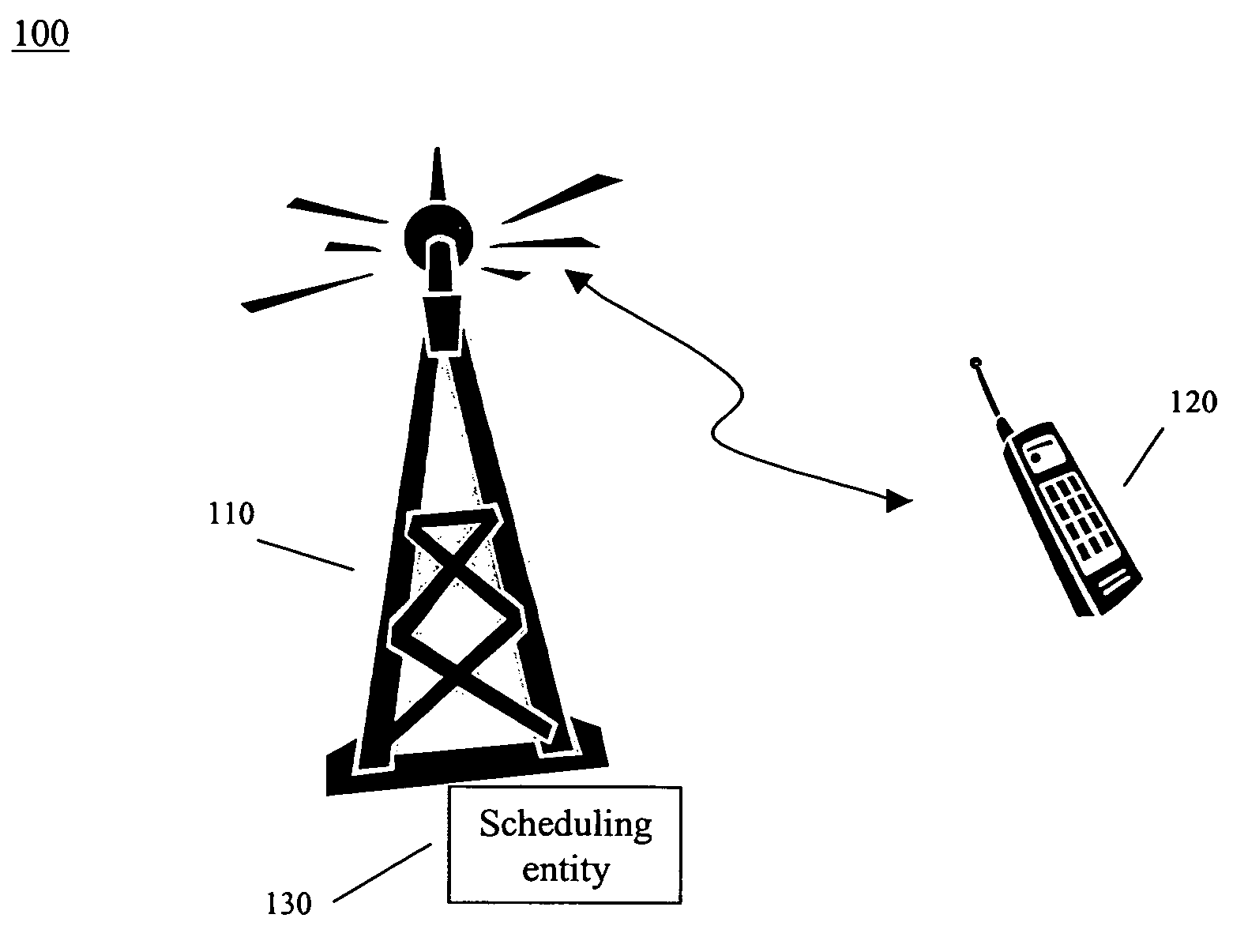
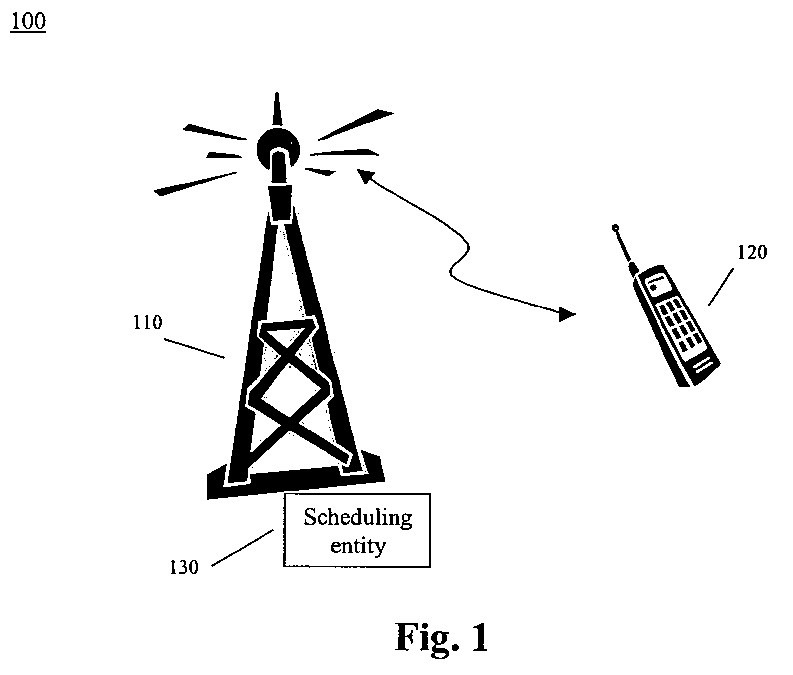
[0013]FIG. 1 depicts a wireless communication system 100 comprising a base station 110 and a mobile station 120 used in accordance with one embodiment of the present invention. Base station 110 includes a scheduler (or other scheduling entity) 130 for allocating sub-carriers to mobile station 120. Data packets are transmitted between base station 110 and mobile station 120 over an Orthogonal Frequency Division Multiple Access (OFDMA) air interface. All data packet transmissions from mobile station 120 to base station n110, i.e., reverse link, are scheduled transmissions.

[0014]Scheduling reverse link data packet transmissions involve scheduler 130 allocating a set of one or more sub-carriers to each mobile station 120 to used for its reverse link transmissions. In one embodiment, the set of allocated sub-carriers include contiguous sub-carriers. The allocated sub-carriers are communicated to mobile station 120 by base station 110 in a scheduling grant or some other message.

[0015]Mobi...


PUM


Abstract

Disclosed is a method of signaling hopping locations selected by a scheduling entity using a frequency hopping pattern indicator for indicating hopping locations for at least two re-transmissions. The frequency hopping pattern is selected by the scheduling entity which may have knowledge of all or at least a plurality of scheduled reverse link transmissions or restrictions upon reverse link transmissions, thereby allowing reverse link re-transmissions to be scheduled in a manner compatible with other reverse link transmissions and restrictions. Overall signaling overhead associated with scheduling re-transmissions is reduced through the signaling of a single message which indicates hopping locations for at least two re-transmissions instead of two or more separate messages, wherein each of the two or more separate message indicates a hopping location for an individual re-transmission.

Description

FIELD OF THE INVENTION[0001]The present invention relates generally to wireless communication systems and, in particular, to frequency hopping in wireless communication systems.BACKGROUND OF THE RELATED ART[0002]Wireless communication systems based on the well-known Universal Mobile Telecommunication System (UMTS) will eventually evolve to a packet data system with an orthogonal frequency division multiple access (OFDMA) air interface. In this evolution, reverse link transmissions of data packets are scheduled. Scheduling reverse link transmissions involves allocating or assigning a set of one or more sub-carriers to a mobile station at every scheduling instance. The sub-carriers allocated to a particular mobile station will be localized in the sense that the allocated sub-carriers are contiguous.[0003]A drawback with localized sub-carrier allocation is that the reverse link transmission is spread over a narrow bandwidth and not spread over a wide bandwidth. Spreading the reverse li...

Claims


Application Information

Patent Timeline
Patent Type & Authority Patents(United States)
IPC IPC(8): H04L12/28
CPCH04L1/0001H04L1/1893H04L5/0094H04L5/0096H04L1/1812H04W72/12
Inventor RAO, ANIL M
Owner ALCATEL LUCENT SAS
Why Eureka
Try Eureka