Frequency-Hopping Method for LTE Aperiodic Sounding Reference Signals

a reference signal and frequency hopping technology, applied in the field of data transmission in mobile communications systems, can solve the problems of consuming a fixed amount of resources for each ue, affecting the ability to achieve, and single shot methodology is potentially much slower than the fast channel upda

Inactive Publication Date: 2012-05-10
RES IN MOTION LTD
View PDF3 Cites 73 Cited by
  • Summary
  • Abstract
  • Description
  • Claims
  • Application Information

AI Technical Summary

Benefits of technology

[0036]Additionally, in certain embodiments, a method by which the eNB can reduce the number of aperiodic configurations that must be defined and signaled to the UE is disclosed. This method defines a minimum set of basis hopping patterns and forces all of the interlaces that the eNB establishes for periodic sounding to conform to one of the basis hopping patterns in the minimum set. Also in certain embodiments, different signaling methodologies may be employed.

Problems solved by technology

Consequently, each UE consumes a fixed amount of resources for that transmission periodically (e.g., every 10 ms) regardless of whether the UE has uplink data to convey or not.
Such a single shot methodology is potentially much slower than the fast channel updates envisioned for aperiodic sounding, which will be triggered using commands at the physical layer.
However, there are certain limitations of the Release 8 / 9 periodic sounding methodology that could potentially complicate the ability to achieve these goals.
However, this parameter does not inform the UE the manner in which the sounding subframes is being used by the eNB.
As discussed, the cell-specific information broadcast as part of the current periodic sounding methodology does not provide a UE with a complete picture of how the various sounding subframes are being used to form interlaces.
However, the scenario shown in FIG. 6 is not valid as this scenario would result in severe interference unless all UEs were only performing wideband sounding.
Thus, the two incompatible sets limit the ability to mitigate the insufficient UE knowledge simply through eNB implementation.
Unfortunately, with two different basis patterns, this can't be done completely.
However, this solution only allows sounding in roughly half of the interlaces, and the eNB scheduler will be somewhat constrained.
The limitations associated with the Release 8 / 9 periodic sounding methodology (i.e., limited information available at the UE and the inability to mitigate this lack of information through eNB implementation) present a plurality of challenges.
While this does reduce the physical layer signaling overhead, it hurts the ability of the eNB to efficiently multiplex aperiodic sounding transmissions within the resources that are not used by the periodic sounding transmissions when those unused resources are such that they will only support narrowband sounding transmissions.
This is because wideband and narrowband transmissions cannot coexist within the same SRS sub-frame (and same transmission comb) without causing mutual interference due to the frequency resources used for each type necessarily overlapping.
This condition can leave some frequency resources on SRS sub-frames unused or vacant whilst forcing the system to set aside more SRS sub-frames to accommodate the wideband aperiodic SRS, thereby reducing the radio resource usage efficiency of the system.
Furthermore, constraining aperiodic SRS to be wideband-only also hurts the channel estimation by forcing many power-limited UEs to sound at a bandwidth that is wider than may be appropriate.
For UEs towards the edge of a cell, or those suffering from high levels of interference at the base station receiver, the finite constraint on UE transmission power can mean that the received signal to noise ratio per unit bandwidth (e.g., per Hz) at the base station is inadequate for channel estimation purposes, rendering the SRS transmission useless.

Method used


Image

  • Frequency-Hopping Method for LTE Aperiodic Sounding Reference Signals
  • Frequency-Hopping Method for LTE Aperiodic Sounding Reference Signals
  • Frequency-Hopping Method for LTE Aperiodic Sounding Reference Signals

Examples


Embodiment Construction

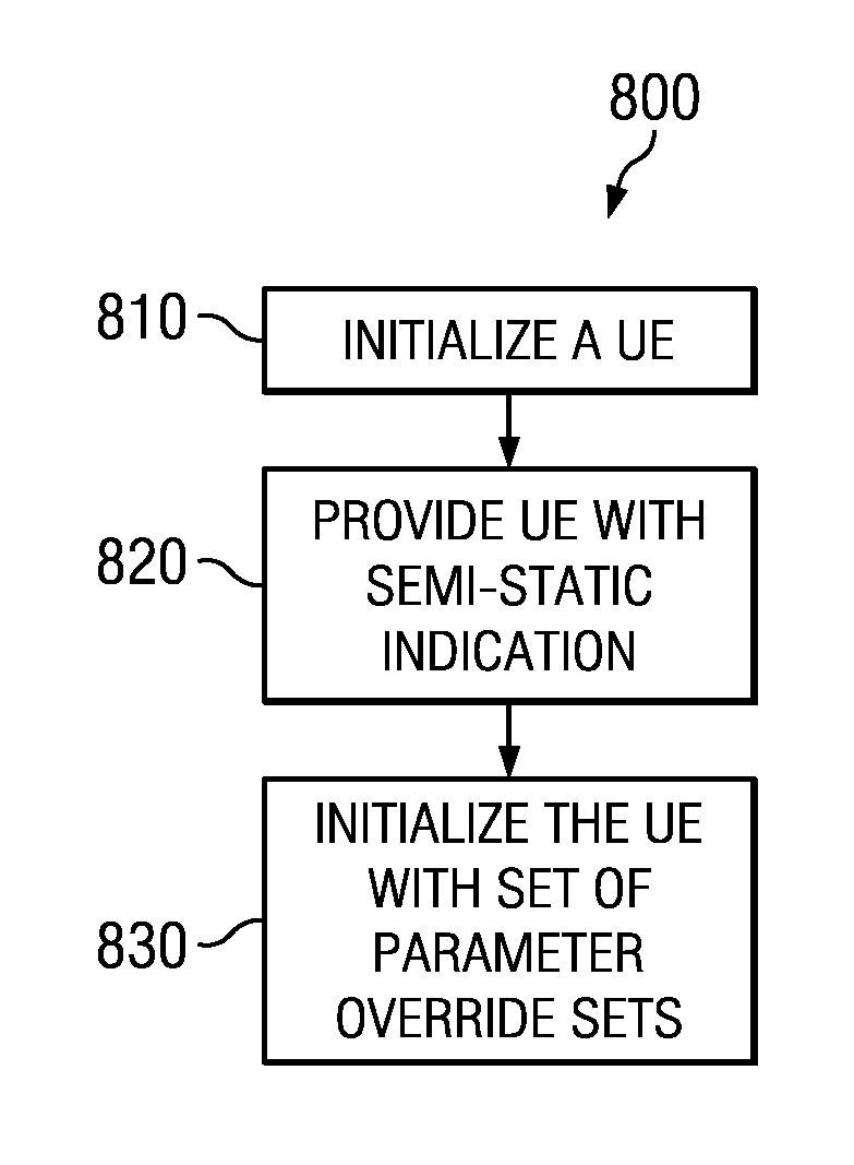
[0056]The present disclosure allows an eNB to define multiple aperiodic sounding reference signaling configurations to be used by a UE. Each of the configurations can employ a different frequency hopping pattern such that all or most of the sounding reference subframes which have been configured with periodic SRS frequency hopping patterns are compatible with the hopping pattern associated with one of the aperiodic configurations.

[0057]This methodology allows the eNB to semi-statically designate which of the defined aperiodic configurations should be used by the UE if aperiodic sounding is triggered in a given subframe. This methodology provides the UE with knowledge of what would be an appropriate hopping pattern in the subframe, while saving the physical layer signaling overhead that would normally be associated with providing bandwidth locations dynamically.

[0058]Note that certain features may be discussed with respect to one of the embodiments, but are applicable to other embodi...


PUM


Abstract

Methods and apparatus are provided to enable aperiodic sounding reference signaling including frequency hopping through the use of additional RRC configuration. The methods can require little or no additional L1 overhead to support narrowband frequency hopping for aperiodic sounding transmissions. In some embodiments, an approach is provided for extending an LTE periodic sounding reference signal methodology to include aperiodic sounding. One benefit of the proposed technique is that it enables each UE to perform aperiodic channel sounding in sounding subframes, using a frequency-hopping pattern, in which the sounding bandwidth of the UE can be narrowed appropriately to match its link capability. Additional benefits of the new approach include better resource utilization, lower signaling overhead, faster channel information update rates, and lower blocking probabilities.

Description

CROSS-REFERENCE TO RELATED APPLICATIONS[0001]This application claims the benefit under 35 U.S.C. §119(e) of U.S. Provisional Application No. 61 / 389,051, filed Oct. 1, 2010, entitled “Frequency-Hopping Method for LTE Aperiodic Sounding Reference Signals,” and under 35 U.S.C. §119(a)-(d) of PCT Patent Application No. PCT / US10 / 58379, filed Nov. 30, 2010, entitled “Frequency-Hopping Method for LTE Aperiodic Sounding Reference Signals.” The disclosures of U.S. Provisional Application No. 61 / 389,051 and PCT Application No. PCT / US10 / 58379 are incorporated herein by reference in their entireties.BACKGROUND[0002]1. Field[0003]The present disclosure generally relates to data transmission in mobile communications systems and more particularly to frequency hopping for aperiodic sounding reference signals.[0004]2. Description of the Related Art[0005]In known wireless telecommunications systems, transmission equipment in a base station or access device transmits signals throughout a geographical ...

Claims


Application Information

Patent Timeline
Patent Type & Authority Applications(United States)
IPC IPC(8): H04B1/713H04W92/00
CPCH04B1/7143H04L27/2636H04L27/2613H04L5/0062H04L27/26H04L5/00
Inventor SMITH, JACK ANTHONYCAI, ZHIJUNGAO, SHIWEI
Owner RES IN MOTION LTD
Why Eureka
Try Eureka