Image forming apparatus with printing processing unit

a technology of image forming apparatus and printing processing unit, which is applied in the direction of electrographic process apparatus, printing, instruments, etc., can solve the problems of reducing and achieve the effect of preventing the availability of conventional image forming apparatus from lowering

Active Publication Date: 2012-09-18
OKI DATA CORP
View PDF8 Cites 2 Cited by
  • Summary
  • Abstract
  • Description
  • Claims
  • Application Information

AI Technical Summary

Benefits of technology

[0009]In the present invention, when the remaining amount of the consumable supply decreases, the printable length determining processing unit determines whether the printable length is smaller than the requested print length. When the printable length determining processing unit determines that the printable length is smaller than the requested print length, the printing processing unit performs the partial printing operation. Accordingly, it is possible to prevent availability of the image forming apparatus from lowering.

Problems solved by technology

In the conventional image forming apparatus, when the host computer determines that the printing operation cannot be preformed, the conventional image forming apparatus cannot perform the printing operation, thereby reducing availability of the conventional image forming apparatus.

Method used


Image

  • Image forming apparatus with printing processing unit
  • Image forming apparatus with printing processing unit
  • Image forming apparatus with printing processing unit

Examples


first embodiment

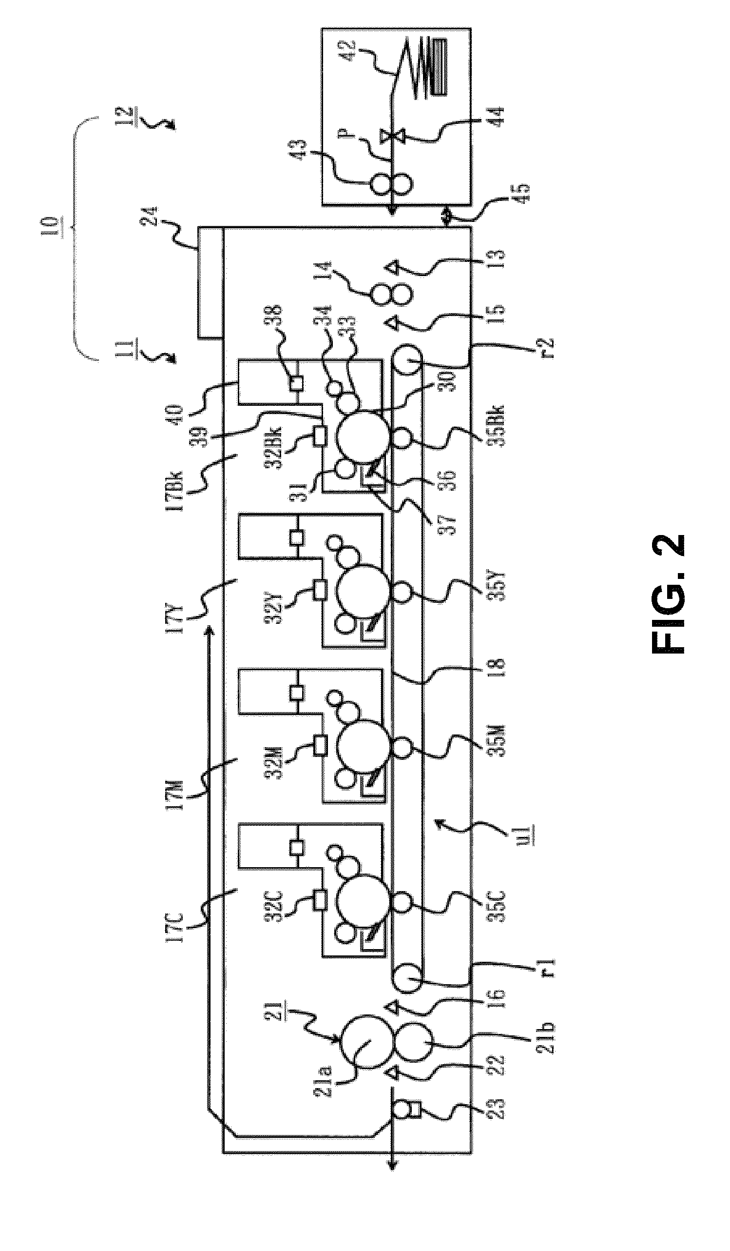
[0026]A first embodiment of the present invention will be explained. FIG. 2 is a schematic sectional view showing the printer 10 according to the first embodiment of the present invention.

[0027]As shown in FIG. 2, the printer 10 includes a printer main body 11; a medium supply mechanism 12 for supplying a continuous sheet P as a medium to the printer main body 11; and a communication cable 45 as a signal line for connecting the printer main body 11 and the medium supply mechanism 12.

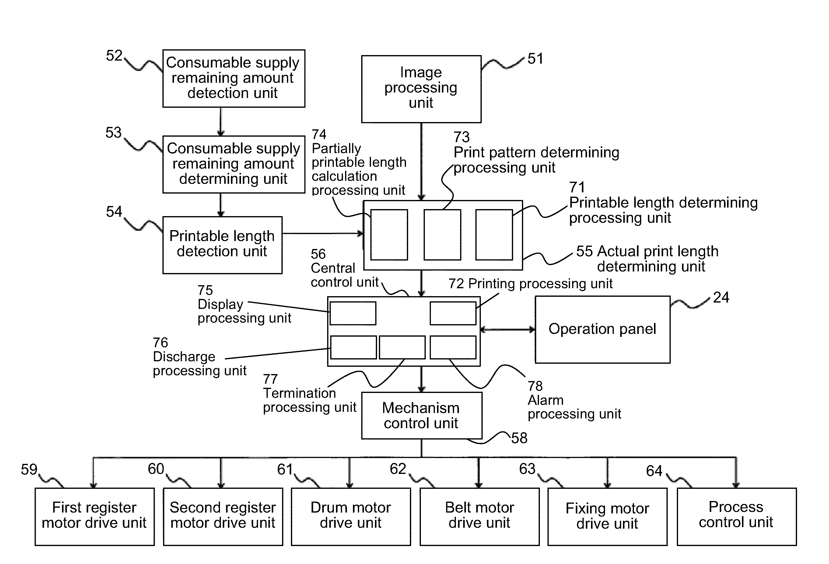
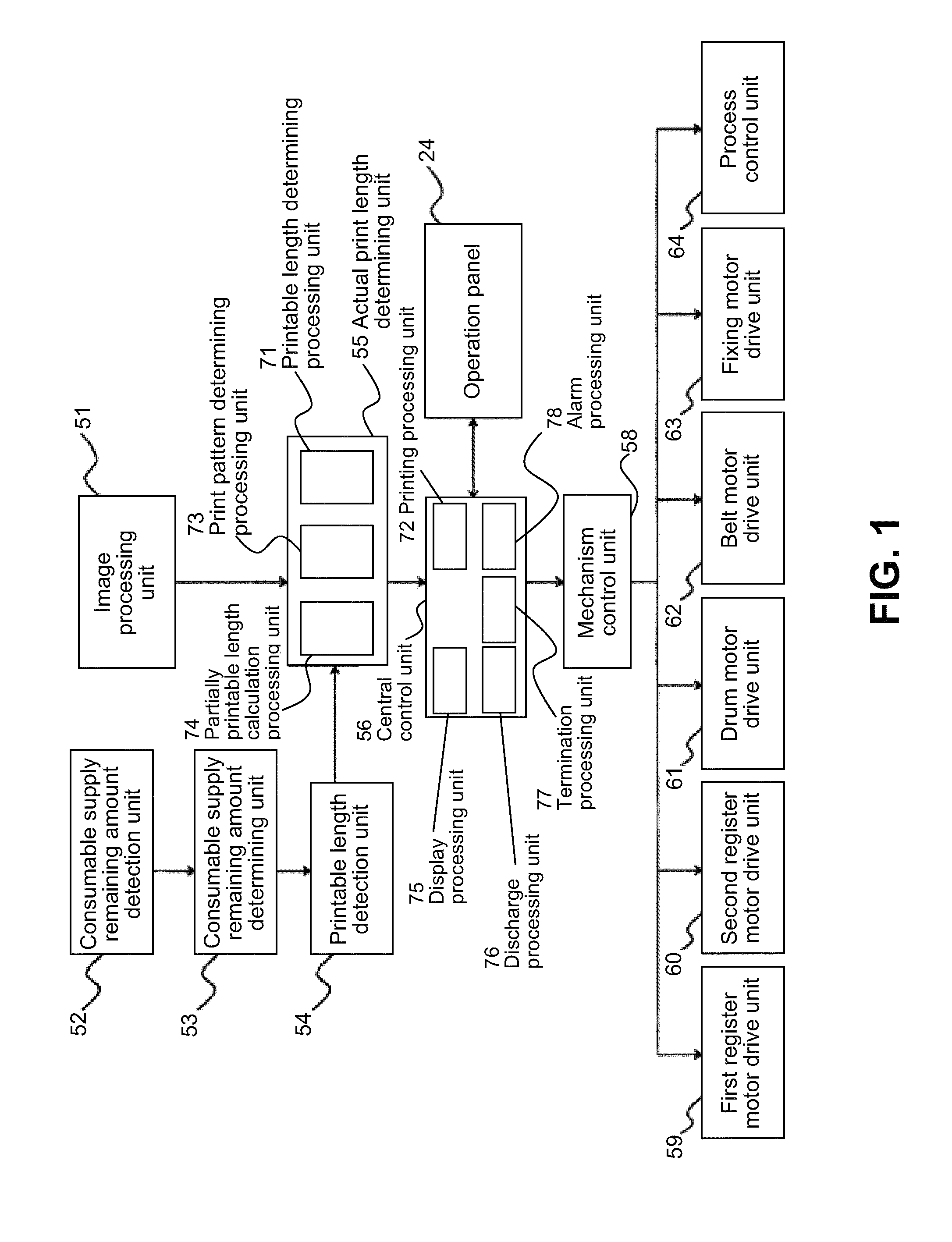
[0028]In the embodiment, the printer main body 11 includes a sheet supply sensor 13 for detecting the continuous sheet P supplied in a transportation direction of the continuous sheet P; a register roller pair 14 as a first register medium transportation unit for correcting skew of the continuous sheet P; a writing sensor 15 as a writing detection unit for detecting a leading edge of the continuous sheet P; image forming units 17Bk, 17Y, 17M, and 17C for forming toner images as developer images in colors...

second embodiment

[0081]A second embodiment of the present invention will be explained. In the second embodiment, the printer 10 is arranged such that the toner cartridge 40 can be replaced while the continuous sheet P stays in the printer 10. Components in the second embodiment similar to those in the first embodiment are designated with the same reference numerals, and explanations thereof are omitted. The components in the second embodiment similar to those in the first embodiment provide similar effects.

[0082]FIG. 13 is a flow chart No. 1 showing an operation of the printer 10 according to the second embodiment of the present invention. FIG. 14 is a flow chart No. 2 showing the operation of the printer 10 according to the second embodiment of the present invention. FIG. 15 is a schematic view showing an example of a printed image according to the second embodiment of the present invention.

[0083]When the operator pushes the permission key, the print processing unit 72 determines that the partial p...


PUM


Abstract

An image forming apparatus includes a consumable supply remaining amount detection unit for detecting a remaining amount of a consumable supply; a printable length detection unit for determining a printable length of a medium printable with the remaining amount; a printable length determining processing unit for determining whether the printable length is smaller than a requested print length of the medium requested with print data; and a printing processing unit for performing a partial printing operation when the printable length determining processing unit determines that the printable length is smaller than the requested print length.

Description

BACKGROUND OF THE INVENTION AND RELATED ART STATEMENT[0001]The present invention relates to an image forming apparatus.[0002]A conventional image forming apparatus such as a printer, a copier, a facsimile, a multi function product, and the likes is connected to a host computer. When an operator operates the host computer to perform a printing operation, the host computer retrieves a state of a consumable supply of the conventional image forming apparatus such as a remaining amount of toner stored in a toner cartridge or a toner remaining amount. Then, the host computer determines whether the printing operation can be preformed according to a print number and the toner remaining amount. When the host computer determines that the printing operation can be preformed, the host computer sends a print instruction to the conventional image forming apparatus. When the host computer determines that the printing operation cannot be preformed, the host computer notifies the operator that the p...

Claims


Application Information

Patent Timeline
Patent Type & Authority Patents(United States)
IPC IPC(8): G03G15/00
CPCG03G15/553G03G15/55G03G2215/00734G03G2215/0888
Inventor SHIRAISHI, TOYOKAZU
Owner OKI DATA CORP
Why Eureka
Try Eureka