Failsafe actuator

Inactive Publication Date: 2012-09-25
GOODRICH ACTUATION SYST
View PDF8 Cites 14 Cited by
  • Summary
  • Abstract
  • Description
  • Claims
  • Application Information

AI Technical Summary

Benefits of technology

[0005]It is an object of the invention to provide an actuator suitable for use as the secondary actuator in the arrangement outline

Problems solved by technology

In such an arrangement there is the risk that failure of the secondary actuator, resulting in jamming thereof, may prevent the strut from reaching its fully deployed, over-centre locked position, thus preventing

Method used


Image

  • Failsafe actuator
  • Failsafe actuator
  • Failsafe actuator

Examples


Embodiment Construction

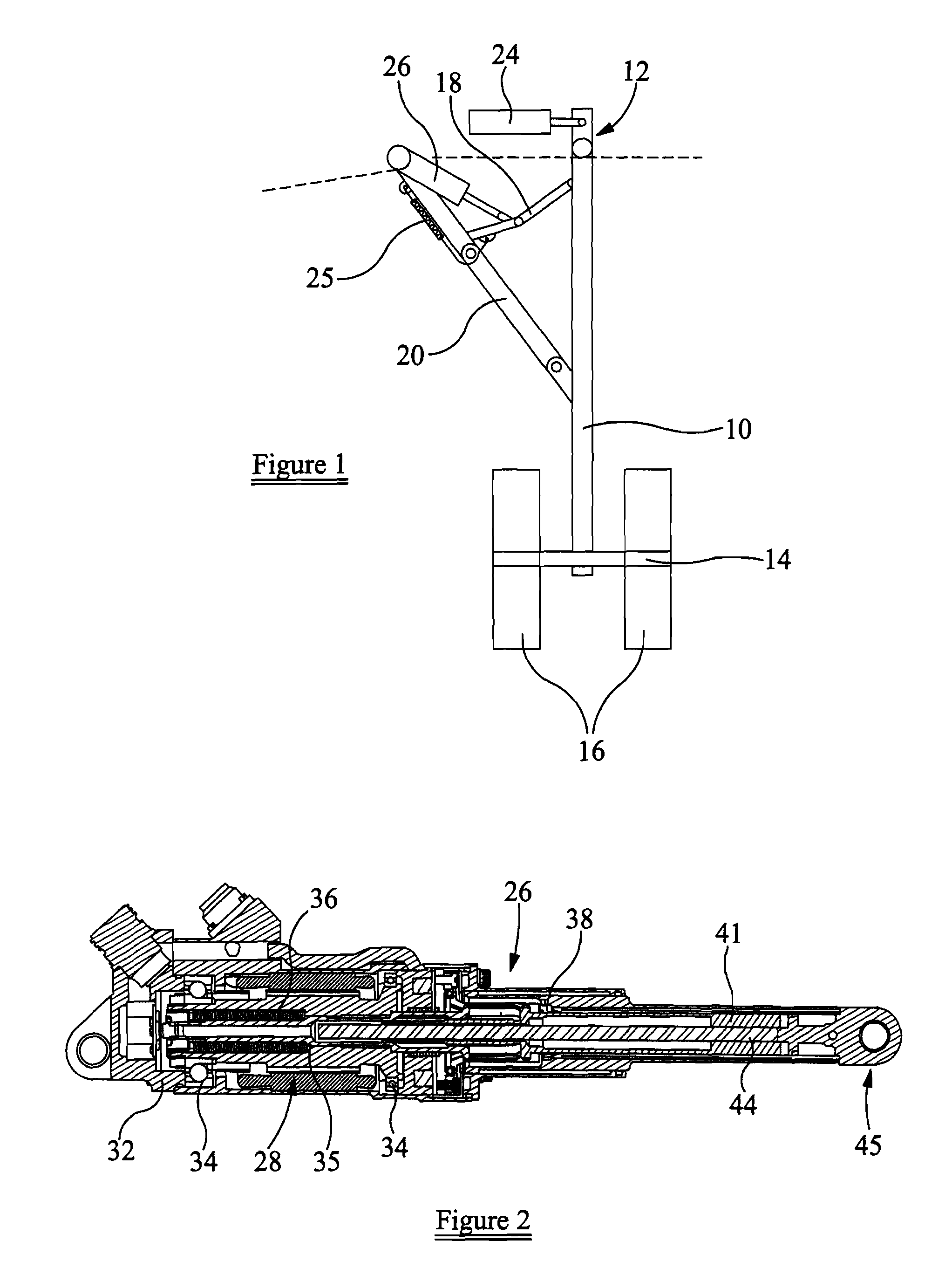
[0021]Referring firstly to FIG. 1 there is illustrated part of the landing gear of an aircraft. The landing gear comprises a support leg 10 which is moveable about a mounting 12 secured to the airframe of an aircraft between a stowed position and a deployed position. The support leg 10 carries, at its lower end, an axle 14 upon which wheels 16 are mounted. A hinged stay 20 is connected between the support leg 10 and the airframe, and a hinged strut arrangement 18 is connected between the stay 20 and the support leg 10. A primary actuator 24 is operable to drive the support leg 10 between its stowed position, in which the strut arrangement 18 is folded, and its deployed position. In moving between these positions, the strut arrangement 18 completely unfolds shortly before the fully deployed position is reached, and then flexes, slightly, in the opposite direction, as the fully deployed position is reached. The slight flexing of the strut arrangement 18 results in the strut arrangemen...


PUM


Abstract

An actuator comprises an actuator shaft mounted for rotation by a drive shaft, releasable lock means operable to restrict axial movement of the actuator shaft relative to the drive shaft, and an output member co-operating with the actuator shaft such that rotation of the actuator shaft drives the output member for translating movement relative to the actuator shaft.

Description

BACKGROUND[0001]This invention relates to an actuator, and in particular to an actuator suitable for use in association with the landing gear of an aircraft, although the actuator may be used in other applications.[0002]The landing gear of an aircraft is typically driven between its stowed and deployed positions by a primary actuator. The weight of the landing gear is sufficient that, during deployment, the primary actuator serves primarily to control the speed of movement of the landing gear under the force of gravity towards the deployed position, the primary actuator also serving to drive the landing gear back towards the stowed position after use. A hinged stay serves to support the landing gear, when at its deployed position, and an over-centre hinged strut is typically provided to hold or lock the landing gear in its deployed position, a spring arrangement being used to drive the strut to its over-centre, locked position.[0003]Due to the provision of the over-centre strut, the...

Claims


Application Information

Patent Timeline
IPC IPC(8): F16H3/06F16H29/20
CPCB64C25/24B64C25/26F16H25/20Y10T74/18688F16H2025/2071F16H2025/2075Y10T74/18704F16H25/2204
Inventor KEARNS, KEITHLANGFORD, DAVID JOHNHUDSON, TIMOTHY
Owner GOODRICH ACTUATION SYST
Why Eureka
Try Eureka