Curve shaft rolling machine

The technology of a rolling machine and a curved shaft is applied in the field of curved shaft processing, which can solve the problems of affecting the roughness and rolling quality of cylindrical shafts, incapable of rolling processing of curved shafts of various diameters, and high manufacturing cost of a third rolling wheel. Achieve the effect of improving rotation flexibility, ensuring positioning, and convenient procurement

Inactive Publication Date: 2010-11-17
南车襄樊机车有限公司
View PDF8 Cites 14 Cited by
  • Summary
  • Abstract
  • Description
  • Claims
  • Application Information

AI Technical Summary

Problems solved by technology

[0003] When the traditional rolling machine rolls the cylindrical shaft, a rolling head is pressed on the shaft to give a radial force to the linear shaft. If the linear shaft is not rigid enough, it is easy to be bent
On the other hand, the rolling wheel can only roll in the direction tangent to the radius of the cylindrical shaft, and cannot roll along the axial direction of the cylindrical shaft. When the rolling head moves axially along the processing axis, there is a gap between the rolling wheel and the shaft. Axial friction will directly affect the roughness and rolling quality of the cylindrical shaft, and it is also easy to cause cracks in the cylindrical shaft during the rolling process. The manufacturing cost of the third rolling wheel is high and the service life is short
The rollers of the fourth rolling machine are fixed, and can only be rolled on cylindrical shafts, but not on curved shafts with various diameters.

Method used


Image

  • Curve shaft rolling machine
  • Curve shaft rolling machine
  • Curve shaft rolling machine

Examples


Embodiment Construction

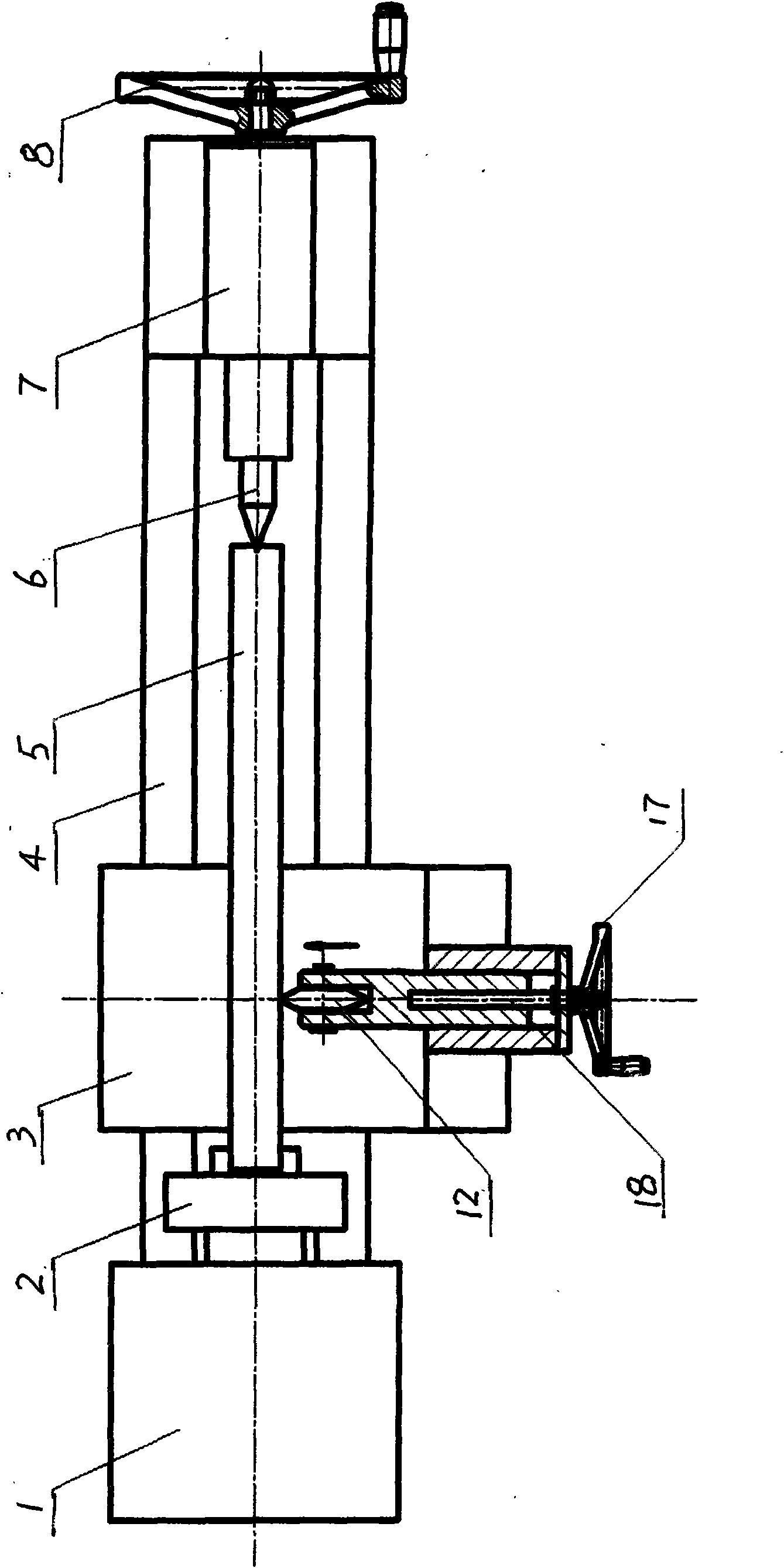
[0010] The structure of the traditional shaft rolling machine is as follows figure 1 shown. It is composed of power box 1, chuck 2, sliding table 3, guide rail 4, top 6, tailstock 7, hand wheel 8, hand wheel 17, screw 18, rolling wheel 12, power box 1 and chuck 2 form a rotating Power mechanism, the top 6 tailstock 7 handwheel 8 constitute the workpiece tightening mechanism, and the slide table 3 guide rail 4 constitutes the horizontal movement mechanism. Working process: First, clamp one end of the cylindrical shaft 5 to be rolled on the chuck, turn the hand wheel 8 to make the tip 6 protrude and tighten the other end of the cylindrical shaft 5; start the power box 1 to make the chuck 2 drive the cylindrical shaft 5 to rotate; The hand wheel 17 drives the screw 19 to rotate to move the rolling wheel 12 to the cylindrical shaft 5 until it is pressed against the cylindrical shaft 5. The rolling wheel 12 rotates with the cylindrical shaft 5 and rolls, and the operator starts th...


PUM


Abstract

The invention relates to a curve shaft rolling machine belonging to the technical field of processing of shaft rolling machinery. The invention mainly solves the problems that single rolling head and rolling wheel of the traditional rolling machine only can rotate in one direction, so that in the shaft rolling and processing procedure, the rolling head and the rolling wheel are pushed and bent, the rolling quality is poor, the shaft range capable of rolling is small, and the like. The curve shaft rolling machine is mainly characterized by comprising a rotary power mechanism, a horizontal movement mechanism, a workpiece proping mechanism and a stand, wherein the rotary power mechanism comprises a power box and a chuck; the horizontal movement mechanism comprises a sliding table and a guide rail; the workpiece propping mechanism comprises a tip, a tailstock and a hand wheel; a group of rolling heads which are symmetrically distributed by a rotary shaft axis are fixed on the sliding table through a bracket, and each rolling head comprises a cylinder body, a piston, a rolling wheel, steel balls, a retaining sleeve and an oil pipe; the cylinder body is fixed on the bracket; the retaining sleeve is fixed on the piston, and the steel balls are arranged at the end part of the retaining sleeve; the rolling wheel is arranged in the retaining sleeve, and the rolling wheel is in contact with the steel balls; and the oil pipe is connected with a hydraulic station. The invention is mainly used for rolling and processing of various curve shafts.

Description

technical field [0001] The invention belongs to the technical field of curved shaft processing, and in particular relates to a curved shaft rolling machine used for rolling curved shafts. Background technique [0002] The traditional shaft rolling machine consists of a power box, a chuck, a sliding table, a guide rail, a top, a tailstock, a hand wheel, a screw, and a rolling wheel. Working process: Firstly, clamp one end of the cylindrical shaft to be rolled on the chuck, turn the hand wheel to make the top stick out and tighten the other end of the cylindrical shaft; start the power box to make the chuck drive the cylindrical shaft to rotate; turn the hand wheel to drive the screw to rotate Move the rolling wheel to the cylinder shaft until it is pressed against the cylinder shaft, the rolling wheel rotates with the cylinder shaft and rolls, the operator starts the sliding table of the rolling machine and moves the rolling mechanism along the guide rail in a straight line a...

Claims


Application Information

Patent Timeline
Patent Type & Authority Applications(China)
IPC IPC(8): B23P9/02
Inventor 任立辉李冬平
Owner 南车襄樊机车有限公司
Why Eureka
Try Eureka