
Terminal pin insertion mechanism of double-framework coil

A technology for inserting mechanism and terminal pins, which is applied in coil manufacturing, metal processing, metal processing equipment, etc. It can solve problems such as low efficiency, inability to achieve continuous pin insertion, cumbersome double coil skeleton pin insertion, etc., and achieve convenient operation , good insertion effect, ingenious effect of structural design

Inactive Publication Date: 2017-12-26
DONGGUAN RONGGONG AUTOMATION TECH CO LTD
View PDF6 Cites 5 Cited by
  • Summary
  • Abstract
  • Description
  • Claims
  • Application Information

AI Technical Summary

Problems solved by technology

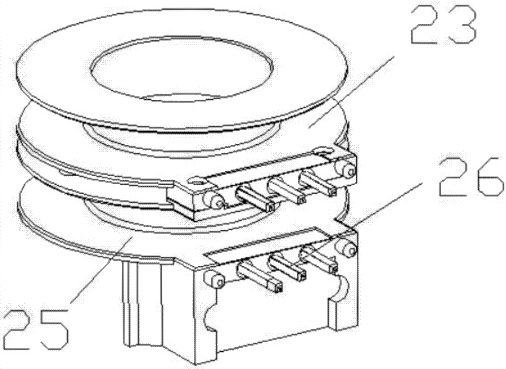
[0002] The motor is a commonly used power component, and its core component is the coil. Most of the existing coils are single-skeleton coils, and the efficiency is not high. In order to improve efficiency, some such as figure 2 The shown double bobbin coil includes an upper bobbin 23 and a lower bobbin 25, both of which need to be inserted into terminal pins 26
[0003] Most of the existing coil bobbins are inserted manually, and some pin insertion equipment has also appeared, but the existing pin insertion equipment needs to fix the coil bobbin first, and then insert the pins through the pin insertion part. The skeleton needs to be taken out manually, and continuous pin insertion cannot be achieved. The pin insertion of the double-coil skeleton is more cumbersome, so it is necessary to design a needle insertion mechanism, which can realize the synchronous and precise pin insertion of the two skeletons of the double-skeleton coil at one time.

Method used


Image

  • Terminal pin insertion mechanism of double-framework coil
  • Terminal pin insertion mechanism of double-framework coil
  • Terminal pin insertion mechanism of double-framework coil

Examples


Embodiment Construction

[0034] In order to enable those skilled in the art to better understand the technical solution of the present invention, the present invention will be described in detail below in conjunction with the accompanying drawings. The description in this part is only exemplary and explanatory, and should not have any limiting effect on the protection scope of the present invention. .

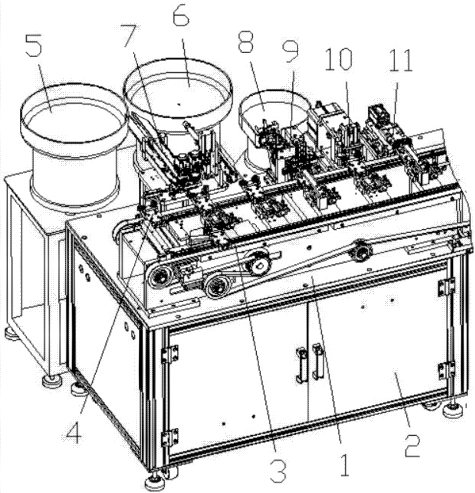
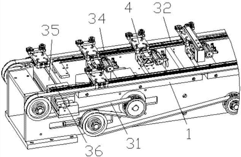
[0035] Such as Figure 1-Figure 11 As shown, the specific structure of the present invention is: a terminal pin insertion mechanism for a double-skeleton coil, which includes a frame 1 and a power distribution control box 2, the frame 1 is provided with a conveying device 3, and the conveying The device 3 is provided with a carrier 4, and the carrier 4 is provided side by side with two clamping posts 38 which cooperate with the skeleton, and the frame 1 is provided with pin insertion devices 9 which cooperate with the carrier 4 in turn. , terminal pin leveling device 10, detection device 11 and skelet...


PUM


Abstract

The invention relates to a terminal pin insertion mechanism of a double-framework coil. A rack is provided with a conveying device, the conveying device is provided with a carrier, two position-clamping columns are arranged on the carrier side by side, the rack is sequentially provided with a pin insertion device matched with the carrier, a terminal pin leveling device, a detecting device and a framework clamping manipulator, the pin insertion device comprises a pin insertion base arranged on the rack, the pin insertion base is provided with two terminal pin conveying grooves, the tail ends of the terminal pin conveying grooves are provided with terminal pin material receiving devices, the terminal pin material receiving devices are matched with the upper and lower frameworks of the carrier through terminal pin material jacking devices, the pin insertion base is provided with a pin-insertion material pressing air cylinder, and the lower portion of the pin-insertion material pressing air cylinder is connected with pin-insertion material pressing block matched with a product on the carrier. According to the terminal pin insertion mechanism of the double-framework coil, through the cooperation between the carrier with the two position-clamping columns and the conveying device, the two frameworks are synchronously conveyed; through the cooperation of the pin insertion device with the two terminal pin conveying grooves, the synchronous pin insertion of the upper and lower frameworks can be achieved, the pin insertion efficiency is improved, and the good insertion effect can be achieved.

Description

technical field [0001] The invention relates to the field of processing equipment for electronic coils, in particular to a terminal pin insertion mechanism for double-skeleton coils. Background technique [0002] The motor is a commonly used power component, and its core component is the coil. Most of the existing coils are single-skeleton coils, and the efficiency is not high. In order to improve efficiency, some such as figure 2 The shown double bobbin coil includes an upper bobbin 23 and a lower bobbin 25 , both of which need to be inserted with terminal pins 26 . [0003] Most of the existing coil bobbins are inserted manually, and some pin insertion equipment has also appeared, but the existing pin insertion equipment needs to fix the coil bobbin first, and then insert the pins through the pin insertion part. The skeleton needs to be taken out manually, and continuous needle insertion cannot be achieved. The needle insertion of the double-coil skeleton is more cumberso...

Claims


Application Information

Patent Timeline
IPC IPC(8): H01F41/10B23P19/027
CPCH01F41/10B23P19/001B23P19/007B23P19/027
Inventor 邓君杨坤
Owner DONGGUAN RONGGONG AUTOMATION TECH CO LTD
Learn More