
Suspension system for vehicle

a suspension system and vehicle technology, applied in the field of vehicles, can solve the problems of difficult to adopt a suspension system and inevitable increase in vehicle height, and achieve the effects of convenient assembly, convenient assembly, and convenient assembly

Active Publication Date: 2013-11-05
HONDA MOTOR CO LTD
View PDF29 Cites 14 Cited by
  • Summary
  • Abstract
  • Description
  • Claims
  • Application Information

AI Technical Summary

Benefits of technology

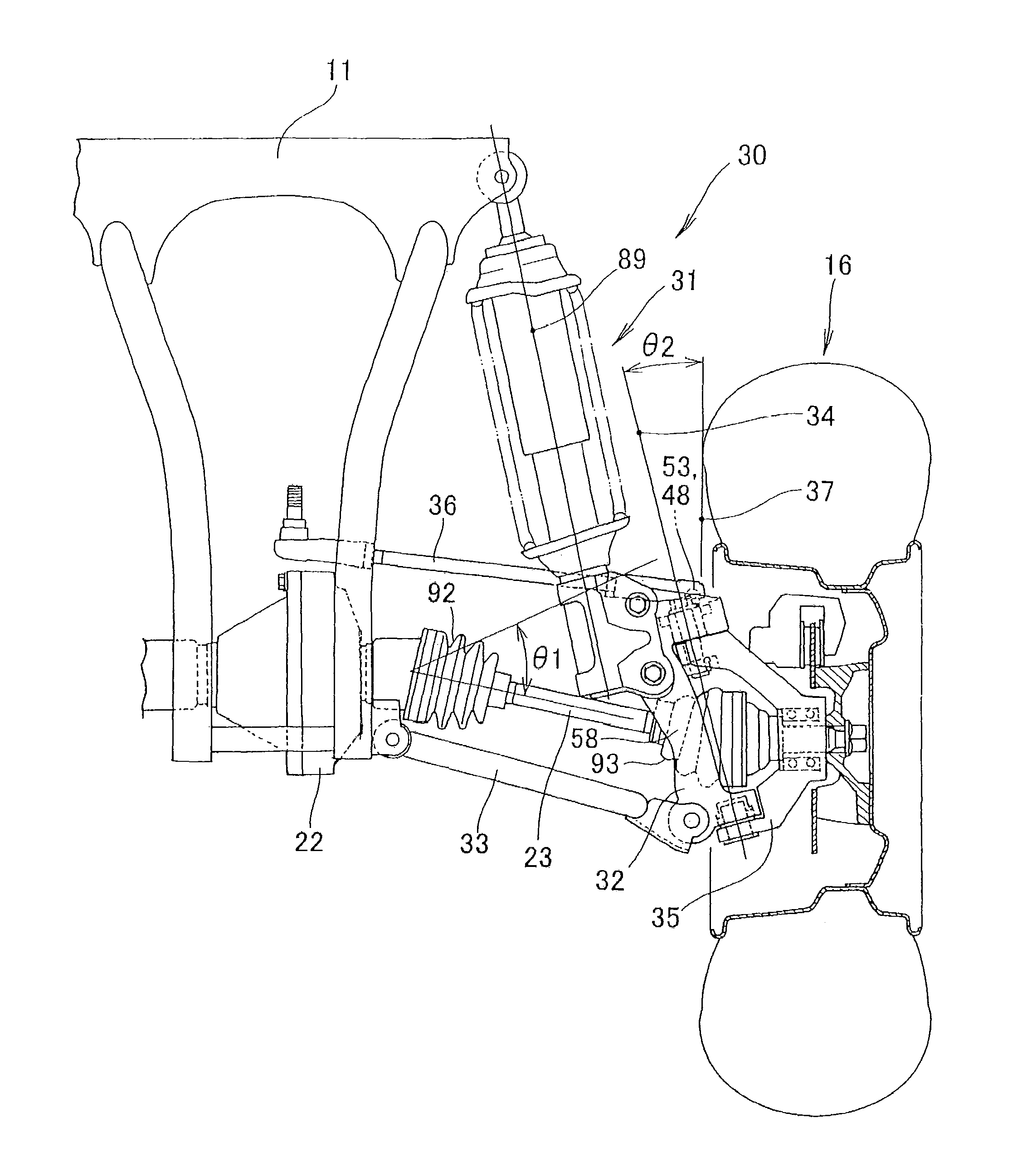
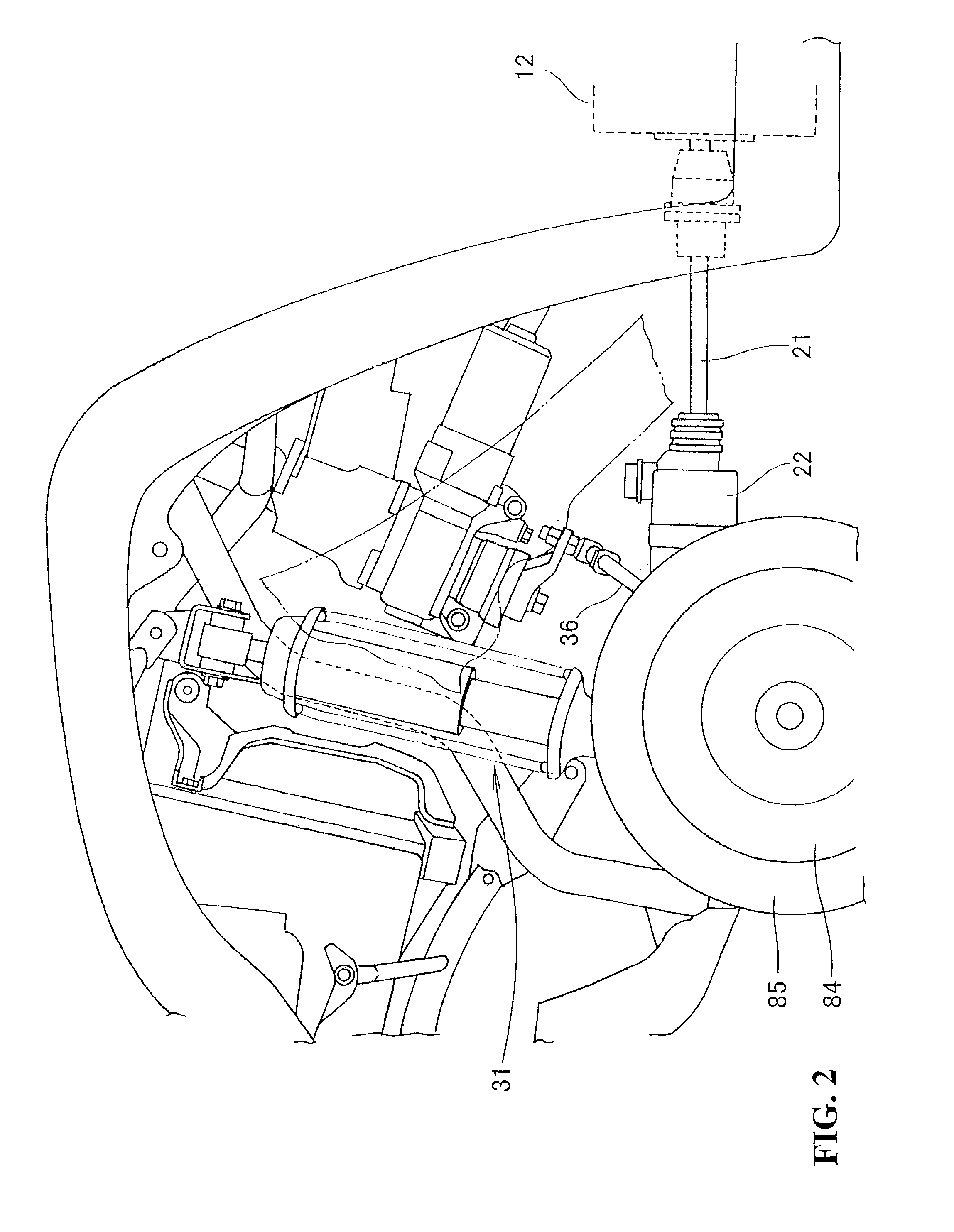
[0022]According to an embodiment of the present invention, the strut damper is arranged in a location in which the downwardly extending line of the axis of the strut damper is located in front of or at the back of the drive shaft. More specifically, as interference between the strut damper and the drive shaft is not a concern, a mounting position of the strut damper can be fully lowered. In addition, the length of the axis of the strut damper can be fully secured. Therefore, the height of the vehicle can be lowered and in addition, the design of the vehicle body is facilitated.
[0034]The position of the upper end of the strut damper is lowered, the vehicle height can be fully lowered, and the center of gravity of the vehicle can be lowered.

Problems solved by technology

However, when the shock absorber (13) described in JP-A No. 2008-302813 is adopted in a vehicle, the vehicle height inevitably becomes high.
That is, it is difficult to adopt a suspension system in JP-A No. 2008-302813 in a small-sized vehicle.

Method used


Image

  • Suspension system for vehicle
  • Suspension system for vehicle
  • Suspension system for vehicle

Examples


Embodiment Construction

[0045]Referring to the drawings, an embodiment of the present invention will be described below. The drawings shall be viewed in a direction of reference signs.

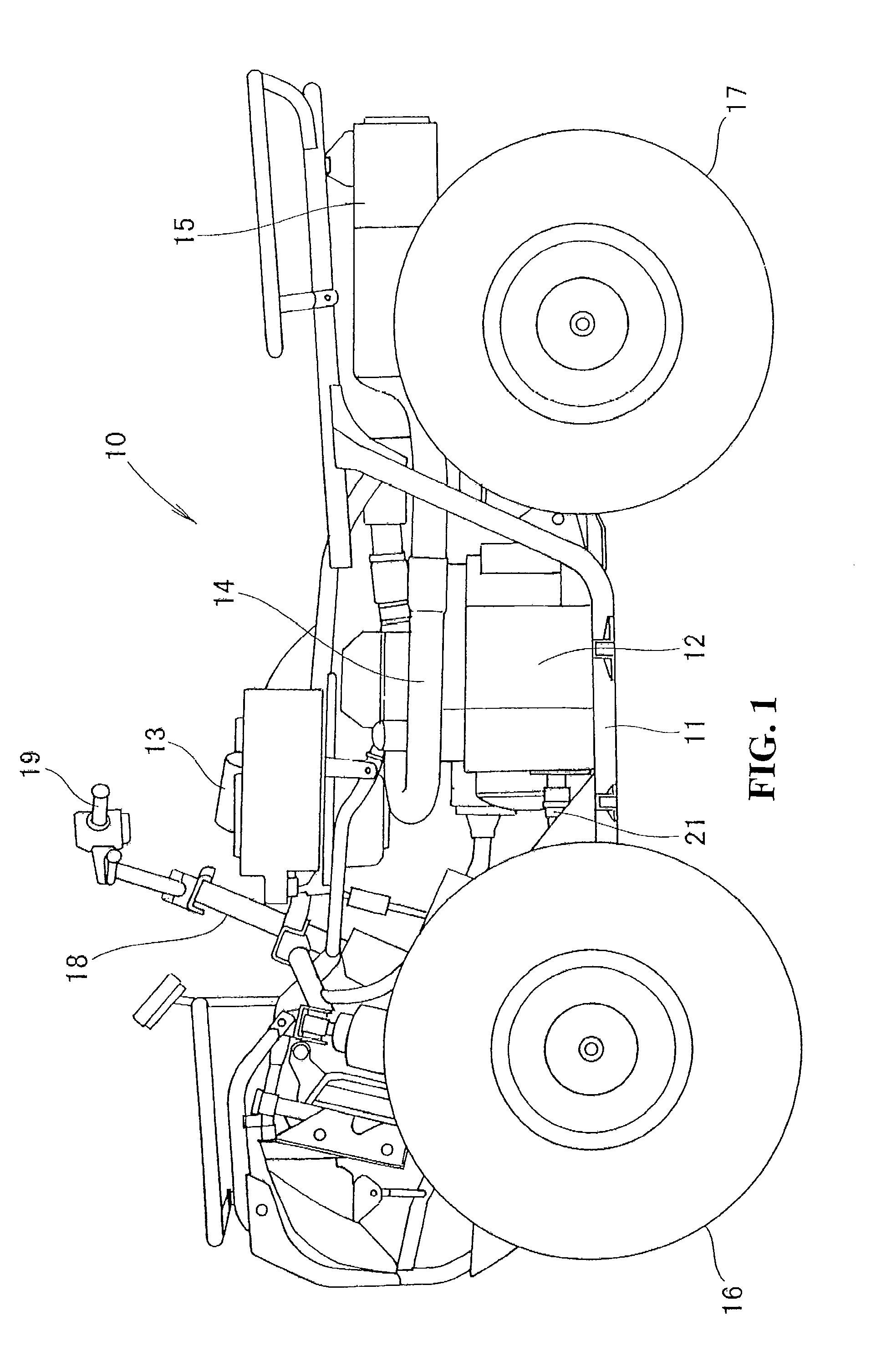
[0046]As shown in FIG. 1, a vehicle 10 is a small-sized vehicle which is provided with a power generation engine 12 such as a gasoline engine in the center of a body frame 11 wherein fuel is mixed with air taken in an air cleaner 13 provided on the body frame 11 and the fuel is combusted in the power generation engine 12 with exhaust gas being exhausted outside via an exhaust pipe 14 extending from the power generation engine 12 and a muffler 15 connected to a rear end of the exhaust pipe 14. Power is transmitted to a front wheel 16 rotatably attached to a lower part of the front of the body frame 11 and / or a rear wheel 17 rotatably attached to a lower part of the rear of the body frame 11 so as to run the small-sized vehicle which can be steered by a steering shaft 18 turnably attached to an upper part of the front of the bo...


PUM


Abstract

A suspension system suitable for a small-sized vehicle such as an all terrain vehicle. A strut damper is arranged wherein a downwardly extending line of an axis of the strut damper is located in front of a drive shaft extending to the depth of a drawing from the rotational center of a front wheel. As interference between the strut damper and the drive shaft is not a concern, a mounting position of the strut damper can be fully lowered. In addition, the length of the axis of the strut damper can be fully secured. Therefore, the height of the vehicle can be lowered. In addition, the design of a vehicle body is facilitated.

Description

CROSS-REFERENCE TO RELATED APPLICATIONS[0001]The present application claims priority under 35 USC 119 to Japanese Patent Application No. 2010-006657 filed on Jan. 15, 2010 the entire contents of which are hereby incorporated by reference.BACKGROUND OF THE INVENTION[0002]1. Field of the Invention[0003]This invention relates to a vehicle, more particularly to a small-sized vehicle provided with a strut damper.[0004]2. Description of Background Art[0005]A strut damper configured by a damper exhibiting damping action and a spring exhibiting restoring action is favorably adopted as a suspension system for a wheel.[0006]Therefore, structures for attaching such strut dampers have been proposed. See, for example, FIG. 2 of JP-A No. 2008-302813.[0007]As shown in FIG. 2 in the JP-A No. 2008-302813, a shock absorber (13) (a numeral in parentheses denotes a reference sign described in JP-A No. 2008-302813, the same hereafter.) is vertically arranged. A downwardly extending line of the axis of t...

Claims


Application Information

Patent Timeline
Patent Type & Authority Patents(United States)
IPC IPC(8): B60G3/04B60G11/26B62D7/06B62D7/18
CPCB60G3/06B60G3/20B62D7/18B62K5/01B60G2200/142B60G2200/144B60G2204/1484B60G2204/4304B60G2206/50B62K2005/001
Inventor KUWABARA, NAOKISEKI, BUNZO
Owner HONDA MOTOR CO LTD
Learn More