Suspension device

a suspension device and shaft technology, applied in the direction of load-engaging elements, transportation and packaging, etc., can solve the problems of difficult positioning of the suspension device, the bearing-mounting tool with respect to the bearing arranged on the shaft, and the suspension device cannot be moved with a cran

Inactive Publication Date: 2012-09-25
SMS DEMAG AG
View PDF9 Cites 1 Cited by
  • Summary
  • Abstract
  • Description
  • Claims
  • Application Information

AI Technical Summary

Benefits of technology

[0009]According to a preferred embodiment of the invention, the damping member is formed as a spring. The advantage of a spring consists in that the spring is a conventional, economical component that can be obtained with a very fine gradation of the stiffness and is easily mountable and dismountable. According to the invention, the spring surrounds the guide rod.
[0010]For adjusting a spring preloads according to the invention, there is provided a tensioning device provided on at least one end of the guide rod for adjusting the preload of the spring. The tensioning device can be formed, e.g., of a spacer sleeve, a hexagonal nut used as a tensioning nut, and a hexagonal nut used as counter-nut. The advantage of the tensioning device according to the invention consist in that in a simple way, a very fine adjustment and correction of the angular position of the bearing-mounting tool with respect to a horizontal, dependent on the applied load, can be carried out. Fine adjustment can cover a relatively large load region, within a preselected load range, within which the suspension device, together with the bearing-mounting tool, is horizontally swingable and very finely adjustable.
[0015]According to the present invention, the base plate of the lifting arm is provided with an elongate opening for receiving the suspending fishplate displaceable and differently positionable in the elongate opening in the base plate. This facilitates the adjustment of the suspension device, together with the bearing-mounting tool.

Problems solved by technology

Because of their large weight, such suspension devices can only be moved with a crane.
The displacement of the gravity center leads to an inclination or slant position of the suspension device, together with the bearing-mounting tool, which makes the positioning of the suspension device, together with the bearing-mounting tool with respect to a bearing arranged on a shaft more difficult.

Method used


Image

  • Suspension device
  • Suspension device
  • Suspension device

Examples


Embodiment Construction

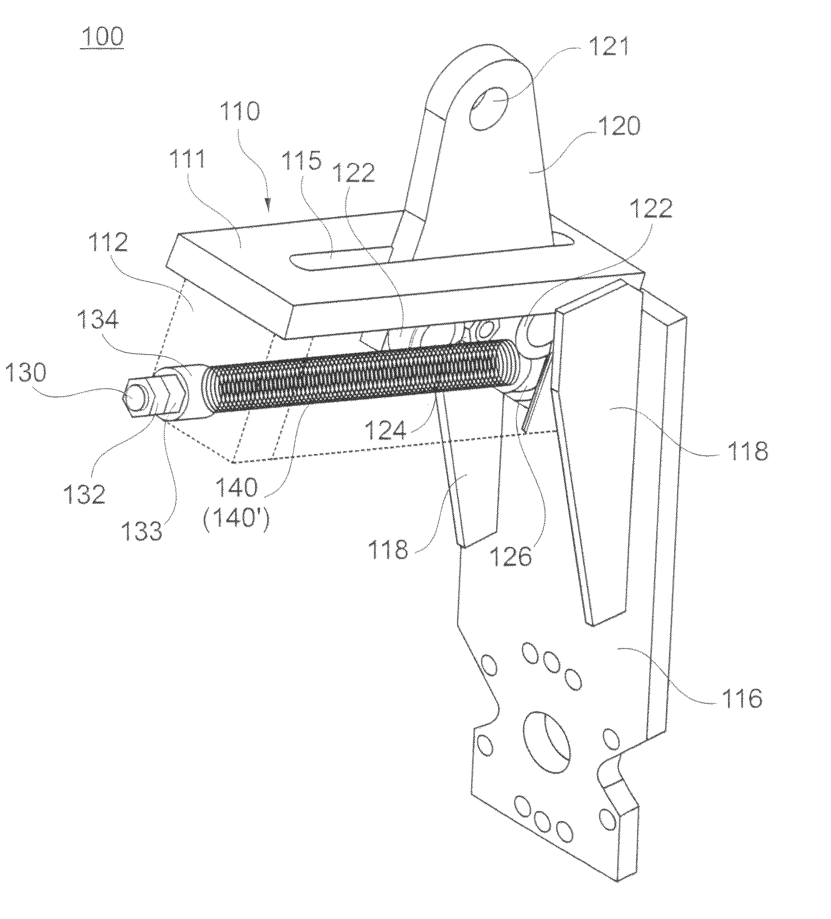
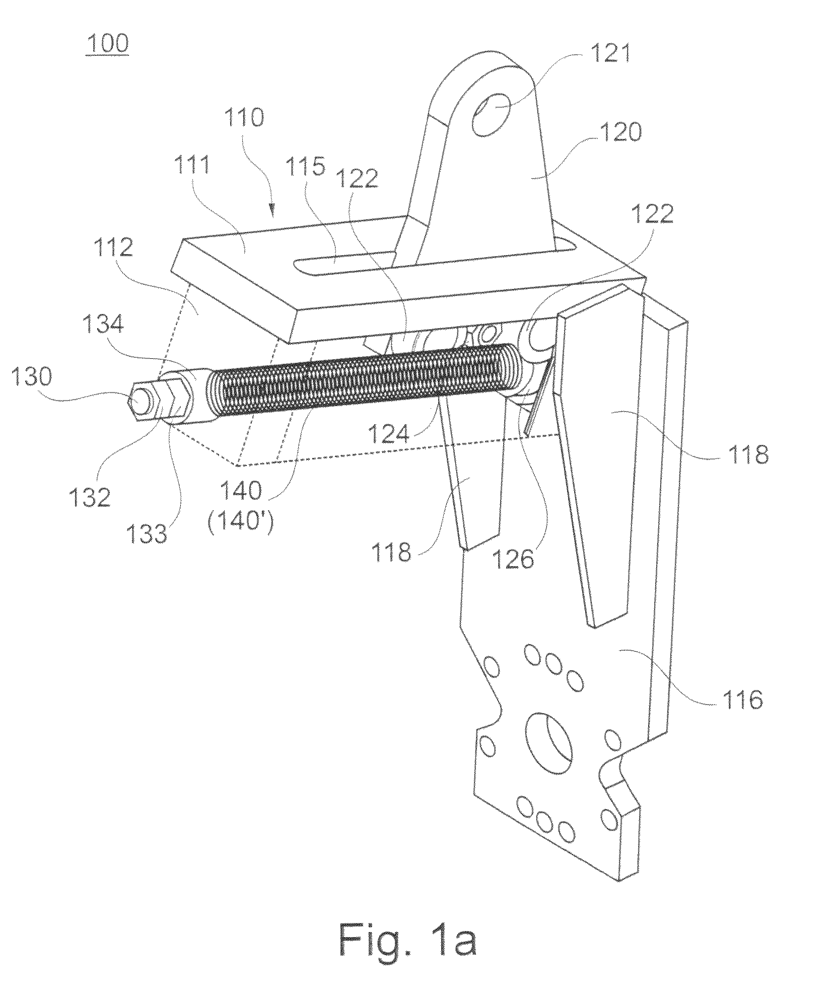
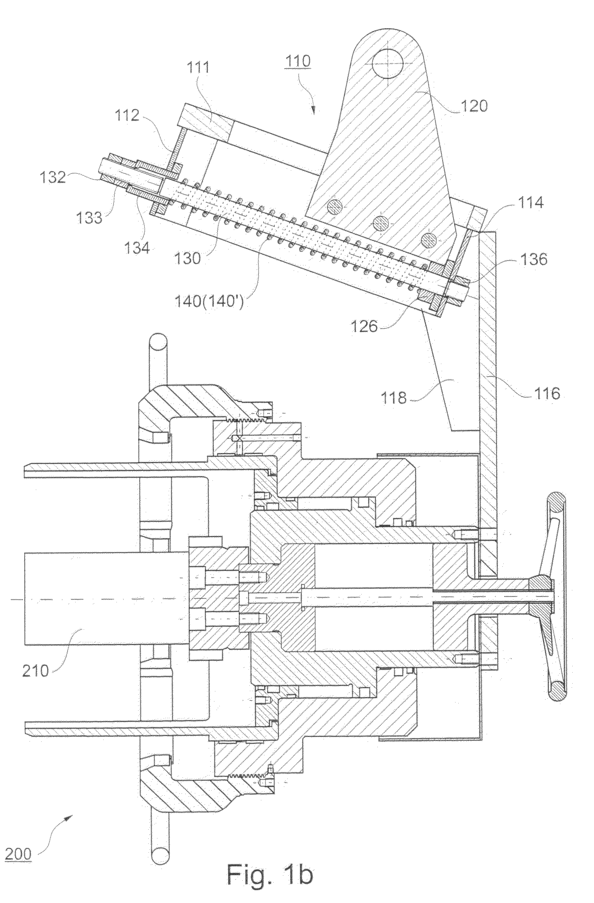
[0026]A suspension device 100 according to the present invention for receiving a load, which is shown in Figs. 1a and 1b, includes a U-shaped lifting arm 110 formed of a base plate 111 and two legs 112, 114 extending at an angle thereto, and a mounting plate 116 arranged on the lifting arm 110. In the embodiment shown in the drawings, the mountings plate 116 is formed for receiving a load in form of a bearing-mounting tool 200, as shown in Fig. 1b.

[0027]At the lower end of the mounting plate 116, there are provided corresponding bores and recesses or guide elements for receiving the bearing-mounting tool 200. For reinforcing the suspension device 100, there are provided web plates 118 that connect the lifting arm 110 with the mounting plate 116. In the base plate 111 of the lifting arm 110, there is provided an elongate opening 115 for receiving a suspending fishplate 120. Each of the legs 112, 114 secured to the base plate 111, has a bore for receiving a guide rod 130. In the embo...


PUM


Abstract

A suspension device for receiving a load includes a U-shaped lifting arm, a mounting plate for receiving a load and provided on the lifting arm, a guide rod extending between the legs of the U-shaped lifting arm, a suspending fishplate displaceable along the guide rod for suspending the suspension device from a lifting / support unit, and a damping member arranged between one of the legs of the U-shaped arm and the suspending fishplate, with a stiffness of the damping member being selected to a predetermined angle to a horizontal.

Description

BACKGROUND OF THE INVENTION[0001]1. Field of the Invention[0002]The present invention relates to a suspension device for receiving a load.[0003]2. Description of the Prior Art[0004]A suspension device for receiving a load is known. An embodiment of such a device is shown in FIG. 4. In FIG. 4, the suspension device 100 is designed for receiving a load in form of a bearing-mounting tool 200. The suspension device 100 has a mounting L-shaped plate 116 to which two legs 112, 114 are welded. Between the legs 112, 114, there is provided a guide rod 130 secured thereto by threaded means. The guide rod is formed as a threaded rod and can be formed as a hexagonal bolt. A suspending fishplate 120 is displaceably supported on the guide rod 130. Because of their large weight, such suspension devices can only be moved with a crane. With the suspension device being suspended on a lifting / support unit, the changing of mass distribution, e.g., upon displacement of a piston 210 within the bearing-mo...

Claims


Application Information

Patent Timeline
Patent Type & Authority Patents(United States)
IPC IPC(8): B66C1/00
CPCB66C1/10
Inventor HUECKER, ROLFSCHEFFE, KURT
Owner SMS DEMAG AG
Why Eureka
Try Eureka