Device for securing the valves of fire posts using the control tube

Inactive Publication Date: 2012-10-02
CAMENE SARL DE DROIT LUXEMBOURGEOIS
View PDF10 Cites 1 Cited by
  • Summary
  • Abstract
  • Description
  • Claims
  • Application Information

AI Technical Summary

Benefits of technology

[0008]This invention has as its object to eliminate these drawbacks by proposing a locking device that is positioned inside the post or the hydrant so as to prevent access to the water, even in the event of voluntary or accidental deterioration of the plug. The device interacts for this purpose with the control tube of the valve so as to prevent the extraction of the plug whether this is toward the outside or toward the inside of the hydrant.

Problems solved by technology

The problem that communities frequently encounter is the theft of water by diversion of water from these hydrants.
None of these solutions is actually effective because in general, these devices are positioned outside of the hydrant and are therefore exposed to all sorts of damage, whereby the latter can range from detachment or pure and simple destruction of the lock and / or the load.

Method used


Image

  • Device for securing the valves of fire posts using the control tube
  • Device for securing the valves of fire posts using the control tube
  • Device for securing the valves of fire posts using the control tube

Examples


first embodiment

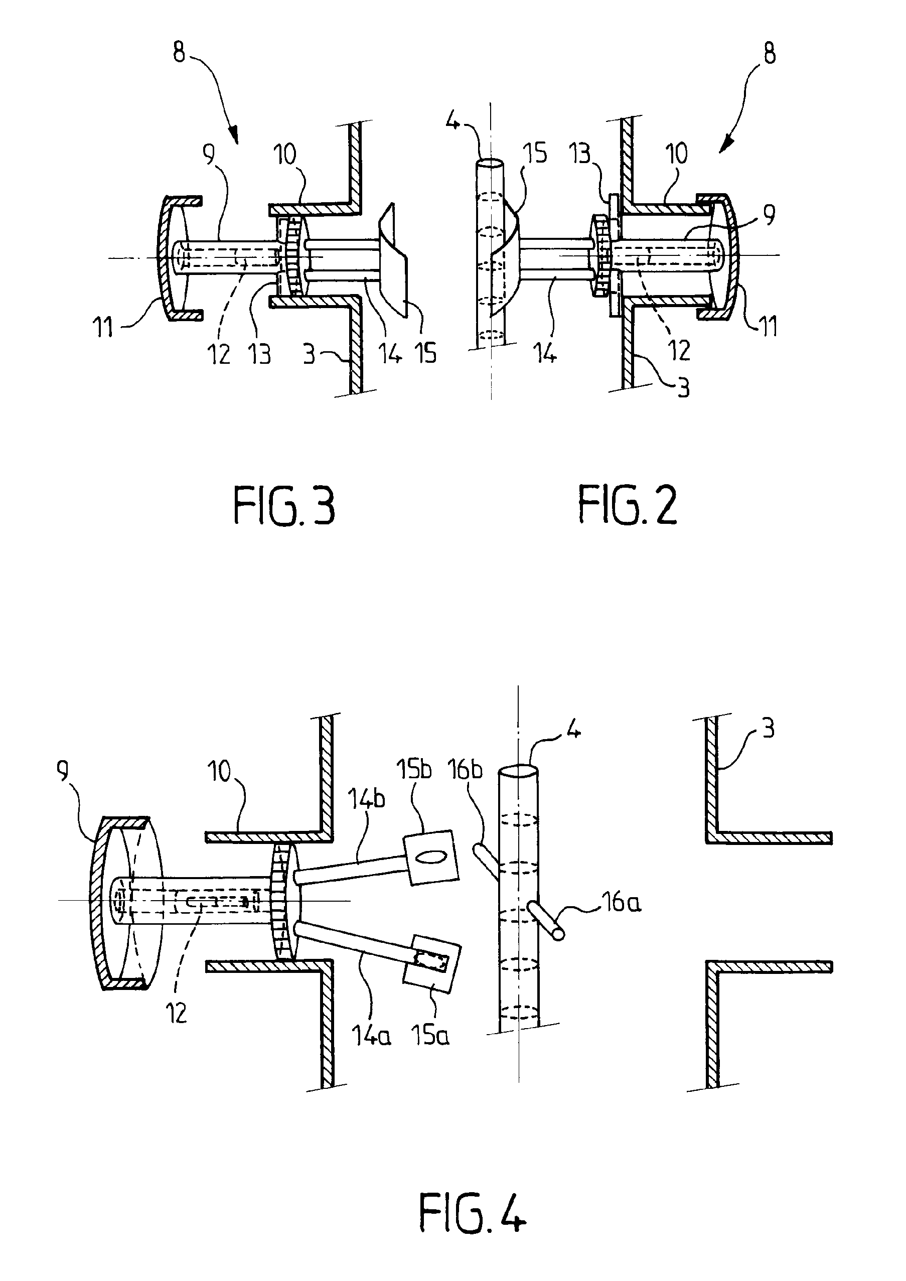
[0038]With reference to FIGS. 2 and 3, a plug 9 for a fire post is seen according to the invention that comprises a cover 11 that can be attached to the hooking device of the cylindrical part 10 of the valve 8. This plug supports a set of elements that are designed to penetrate the interior of the valve 8 so as to prevent its detachment or its sinking. First of all, a locking device 12 such as a lock that can be activated by a key (not shown) that controls bolts 13 that can firstly be separated from the shaft of the plug to prevent the removal of the plug and can secondly be retracted from the inside of said plug to release it from the valve is attached to this plug. These bolts are positioned here so that they are used in a locked position inside the pipe 3. The plug 9 also supports, beyond these bolts, a support 14 that extends in the direction of the control tube 4. A palette 15, which essentially rests on the control tube 4 when the plug is locked on the valve 8, is attached to ...

second embodiment

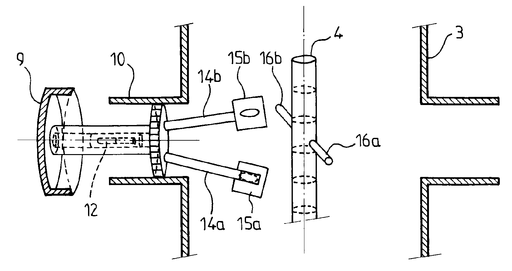
[0041]In a variant of this second embodiment, which also achieves better securing of the hydrant, the parts 14a and 14b can be separated from the shaft of the plug once they have penetrated inside the pipe 3; they can then, once the plug 9 has been installed, be brought toward one another under the action of, for example, the key of the lock 12, so as to enclose the two studs 16a and 16b. In this variant, the palettes 15a and 15b have a shape that is suitable for enclosing the studs, such as that of a ring or a scooped-out cone. Just as above, in this variant, the bolts 13 are not needed (or kept for the sake of redundancy), whereby their function to prevent the extraction of the plug is already ensured by the palettes 15a and 15b.

third embodiment

[0042]With reference to FIGS. 5 to 7, the invention will now be described. This embodiment is particularly well suited to the leveling of the existing installations since it requires only a tapping of the control tube and the installation of a buffer on the latter, and it does not provide a modification of the valve. The attachment of the buffer is shown in the figure by means of a screwing but could equally possibly be done by clamping or by gluing.

[0043]The plug 9 has a cylindrical shape whose upper part is scooped out for forming two lateral appendices 17 that are separated from one another by a hollow part whose bottom constitutes the palette 15 that is designed to rest on the control tube 4 and to prevent the sinking of the plug into the valve. The two appendices 17 have the function of clamping the control tube 4 so as to ensure the centering of the plug and, secondarily, preventing its rotation around the axis of symmetry of the cylinder.

[0044]On the cylindrical part of the p...


PUM


Abstract

The invention relates to a device for securing a fire hydrant, comprising a duct (3), a control pipe (4) having an operation end piece (5) at one end and a valve (7) at the other end capable of supplying said duct (3) with water from the main network, at least one connection (8) attached to said duct and capable of receiving fire hoses, said connection (8) including a sealing plug (9), said plug (9) including at least one first retaining means (15, 15a, 15b) capable of interacting with the control pipe (4) or with a wall of said duct (3) so as to prevent the sinking of the plug into said connection, characterized in that said plug (9) includes at least a second retaining means (13) for preventing the extraction of the plug from said connection and actuated by a locking device (12).

Description

BACKGROUND OF THE INVENTION[0001]1. Field of the Invention[0002]The field of this invention is that of firefighting means and in particular water supply terminals, such as fire posts and fire hydrants, combined under the generic term of hydrants.[0003]2. Description of the Related Art[0004]A fire post is, as its name indicates, a hollow post in which a set of controls is arranged and which allows the channeling of pressurized water from the primary supply network to the firefighting personnel. The post is equipped with valves to which the firefighters come to connect their hoses, which are sealed by plugs when they are not in use. Using a wheel, fixed or movable, or a key that is fitted to a maneuvering end fitting, the controls make it possible to move the check mechanism of a spigot, referred to as a valve, which is placed downstream from the pipe for channeling the water and whose opening causes the water to be made available. The post very often is enclosed in a hood that is equ...

Claims


Application Information

Patent Timeline
IPC IPC(8): E03B9/02
CPCE03B9/08E03B9/04Y10T137/5485Y10T137/5468
Inventor VASCONI, BERTRAND
Owner CAMENE SARL DE DROIT LUXEMBOURGEOIS
Why Eureka
Try Eureka