Anisotropy orientation image from resistivity measurements for geosteering and formation evaluation

an anisotropy orientation and resistivity measurement technology, applied in the field of oil field exploration, can solve the problems of complex determination of electrical anisotropy and insufficient anisotropy characterization techniques presently availabl

Active Publication Date: 2012-10-02
BAKER HUGHES INC
View PDF9 Cites 29 Cited by
  • Summary
  • Abstract
  • Description
  • Claims
  • Application Information

AI Technical Summary

Problems solved by technology

Due to physical complexities of the formation, determining the electrical anisotropy can be complicated.
Unfortunately, techniques presently available do not adequately provide for characterization of anisotropy while drilling.

Method used


Image

  • Anisotropy orientation image from resistivity measurements for geosteering and formation evaluation
  • Anisotropy orientation image from resistivity measurements for geosteering and formation evaluation
  • Anisotropy orientation image from resistivity measurements for geosteering and formation evaluation

Examples


Embodiment Construction

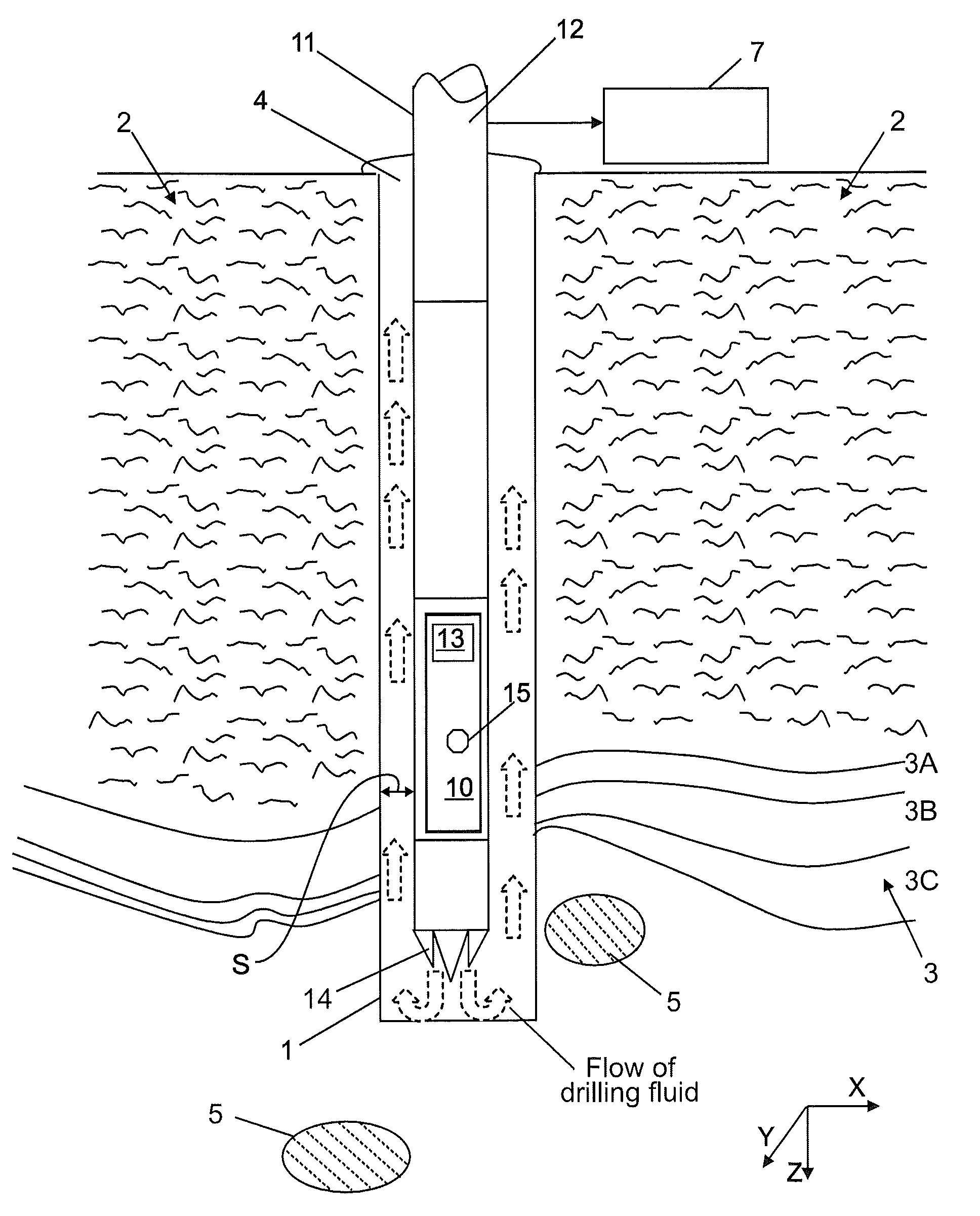
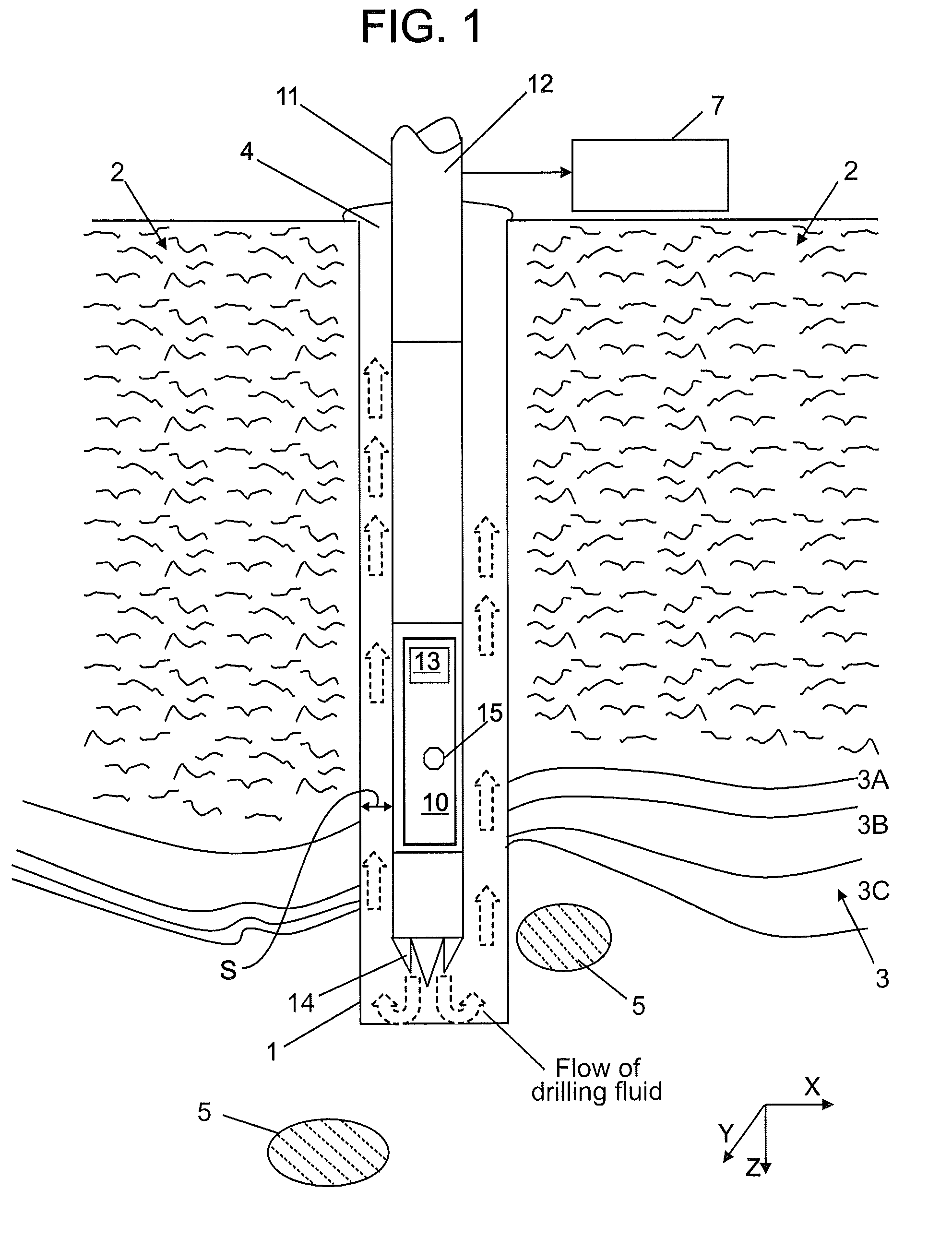
[0023]Disclosed are methods and apparatus for estimating variation of anisotropy, relative dip and azimuth of formations encountered in oil field exploration. The techniques presented make use of resistivity measurements, including main and cross components of the resistivity measurements. The results provide users with meaningful data such as may be used as an input for geosteering or subsequent formation evaluation. Images generated using the technology provided herein may be color coded to aid in interpretation.

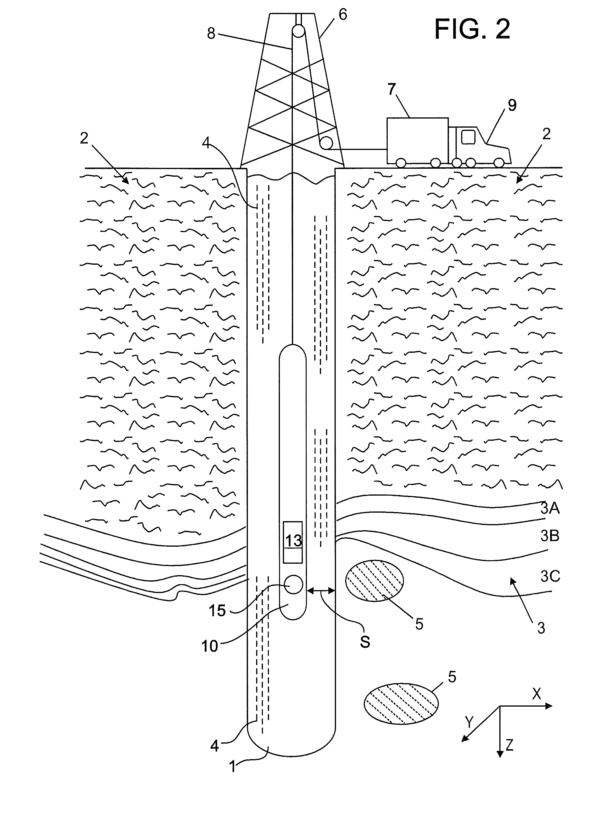
[0024]Refer now to FIG. 1 where aspects of an apparatus for drilling a wellbore 1 (also referred to as a “borehole”) are shown. As a matter of convention, a depth of the wellbore 1 is described along a Z-axis, while a cross-section is provided on a plane described by an X-axis and a Y-axis.

[0025]In this example, the wellbore 1 is drilled into the Earth 2 using a drill string 11 driven by a drilling rig (not shown) which, among other things, provides rotational energy and d...


PUM


Abstract

A method for providing an image of a formation surrounding a wellbore, includes: obtaining an apparent conductivity curve from main components of resistivity measurements of the formation; performing fitting for cross-components of the resistivity measurements; calculating scaling factors from the cross-component data; scaling apparent conductivity data by the calculated scaling factors; and plotting the scaled conductivity data to provide the image of the anisotropic formation. A system and a computer program product are disclosed.

Description

CROSS REFERENCE TO RELATED APPLICATION[0001]This application is a Non Provisional application of U.S. Provisional Ser. No. 61 / 080,441, filed Jul. 14, 2008, the contents of which are incorporated by reference herein in their entirety.BACKGROUND OF THE INVENTION[0002]1. Field of the Invention[0003]The invention is related generally to oil field exploration and in particular to use of at least one of multi-component induction measurements and propagation measurements for geosteering and formation evaluation.[0004]2. Description of the Related Art[0005]Electromagnetic induction and wave propagation logging tools are commonly used for determination of electrical properties of formations surrounding a borehole. These logging tools give measurements of apparent resistivity (or conductivity) of the formation that, when properly interpreted, are diagnostic of the petrophysical and other properties of the formation and the fluids therein.[0006]In various environments, such as those having thi...

Claims


Application Information

Patent Timeline
Patent Type & Authority Patents(United States)
IPC IPC(8): G01V3/00
CPCG01V3/28
Inventor FANG, SHENGKIRKWOOD, ANDREW D.MERCHANT, GULAMABBASHART, ERICWANG, TSILI
Owner BAKER HUGHES INC
Why Eureka
Try Eureka