System and method for displaying data associated with subsurface reservoirs

a technology for subsurface reservoirs and data, applied in seismology, waterlogging instruments, reradiation, etc., can solve the problems of difficult to locate (e.g., land) the wellbore in a desired location, and the formation properties are not effectively modelled and visualized far away from the tool location, so as to achieve quantitative and effective display of partial information

Active Publication Date: 2013-01-29
SCHLUMBERGER TECH CORP
View PDF21 Cites 30 Cited by
  • Summary
  • Abstract
  • Description
  • Claims
  • Application Information

AI Technical Summary

Problems solved by technology

These geosteering solutions, however, do not effectively model and visualize formation properties far away from the tool locations.
Thus, in some earth formations, the formation properties and boundary locations far away from the tool location are only partially determined from the measurements, and it is difficult to locate (e.g., land) the wellbore in a desired section of the reservoir that maximizes economic production without quantifying and effectively displaying this partial information.

Method used


Image

  • System and method for displaying data associated with subsurface reservoirs
  • System and method for displaying data associated with subsurface reservoirs
  • System and method for displaying data associated with subsurface reservoirs

Examples


Embodiment Construction

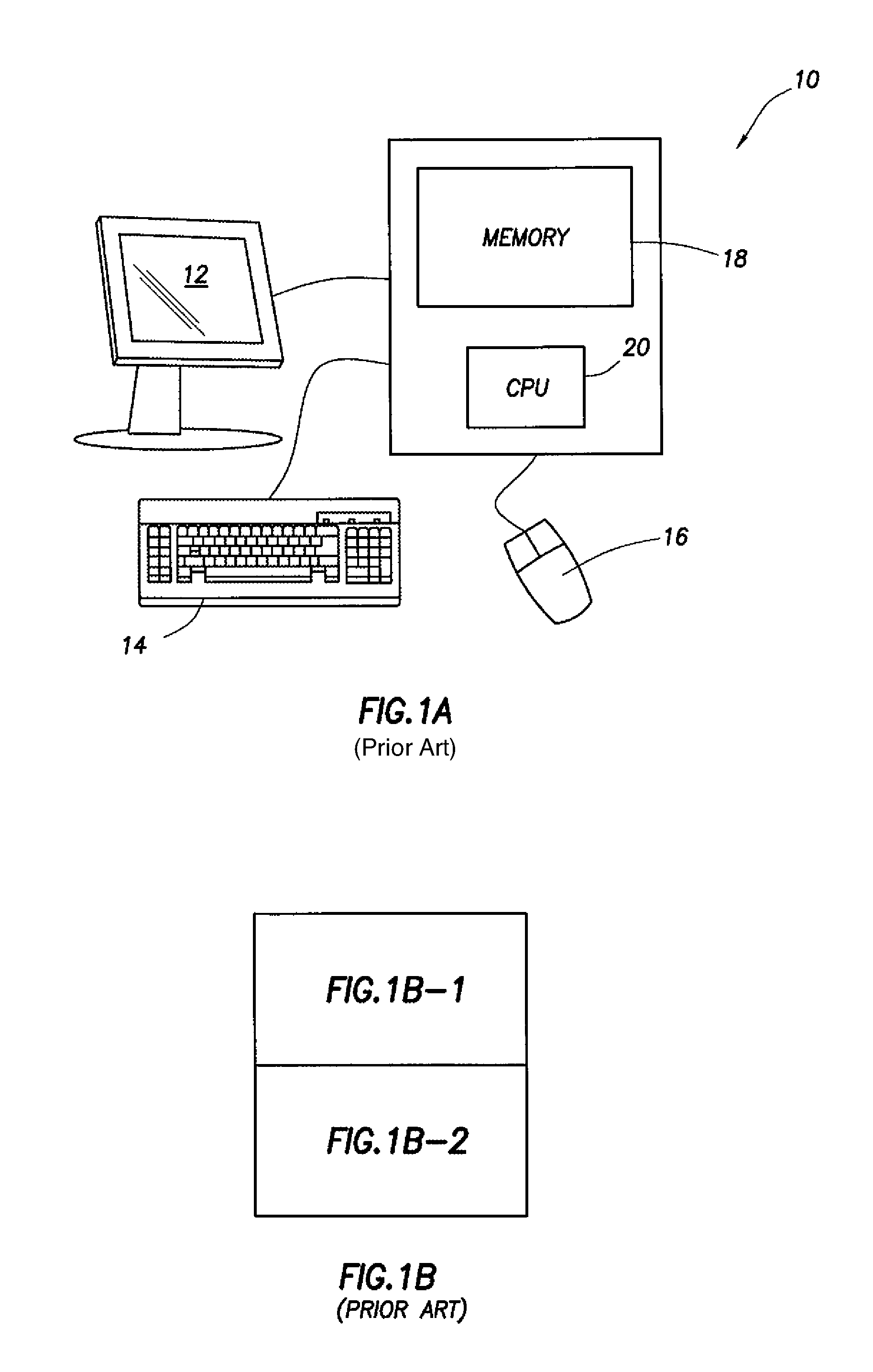
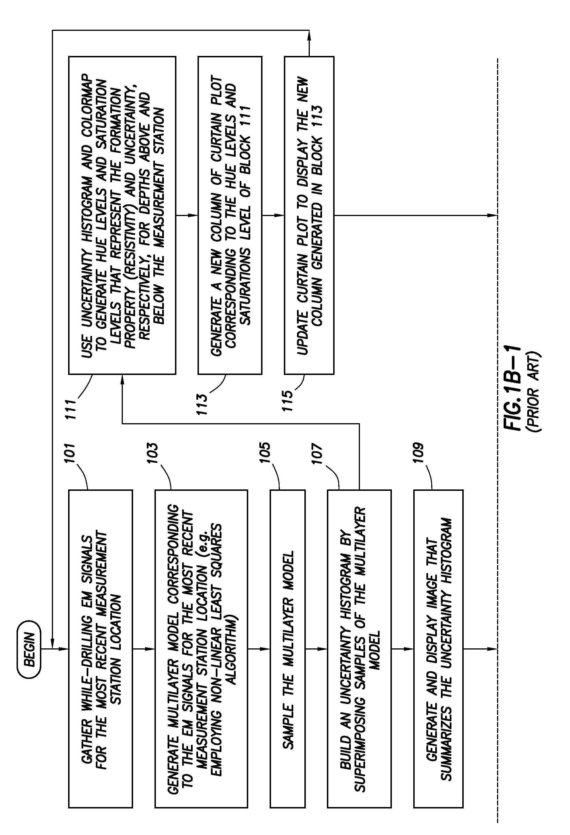
[0041]In the following detailed description of the preferred embodiments, reference is made to the accompanying drawings, which form a part hereof, and within which are shown by way of illustration specific embodiments by which the invention may be practiced. It is to be understood that other embodiments may be utilized and structural changes may be made without departing from the scope of the invention.

[0042]Systems and methods are disclosed herein for displaying one or several attributes derived from a mathematical process used in a modeling estimation that can, in combination with other real time display data, contribute to a clearer picture of formation / reservoir structure and location of fluid contacts. These systems and methods may provide real time visual information or maps about the position of the drilling assembly with respect to reservoir markers (such as reservoir top and bottom, oil / water contact, gas / water contact, or gas / oil contact) that is easy to interpret and use...


PUM


Abstract

Method and system for visualizing one or more properties of a subterranean earth formation while drilling a borehole using probability information from a modeling process. Probability waveforms based on information from a plurality of borehole stations may be plotted, either alone or superimposed onto other graphical representations, to provide a visual display that is easily interpreted by a user to make geosteering decisions. The probability waveforms include peaked sections that are proportional to the amount of uncertainty or error associated with a boundary estimate at a particular distance from an axis of the borehole. By providing a visual display of the uncertainty, a user can make better geosteering decisions.

Description

BACKGROUND[0001]1. Technical Field[0002]The present disclosure relates generally to the field of measurement-while-drilling tools. More particularly, this disclosure relates to methods for processing signals from a measurement-while-drilling tool to model and visualize layered subterranean earth formations surrounding the tool.[0003]2. Description of the Related Art[0004]Wellbores drilled through earth formations to extract fluids such as petroleum are frequently drilled along a substantially horizontal trajectory in a reservoir in order to increase the drainage area in the reservoir. Because such reservoirs are frequently located in layered subterranean earth formations, the position of the substantially horizontal wellbore relative to the boundaries of the layers in the earth formation often has a material effect on the productivity of such wellbores.[0005]Geosteering solutions have been developed that utilize a measurement-while-drilling tool to provide for real-time prediction a...

Claims


Application Information

Patent Timeline
Patent Type & Authority Patents(United States)
IPC IPC(8): G01V3/38G01V9/00G01V1/40G01V3/18
CPCG01V1/50G01V3/18G01V3/38
Inventor LEGENDRE, EMMANUELTABANOU, JACQUES R.SEYDOUX, JEANITO, KOJILEGENDRE, FABIENNEKUTIEV, GEORGI
Owner SCHLUMBERGER TECH CORP
Why Eureka
Try Eureka