Can dispenser for a carton

a dispenser and carton technology, applied in the field of cartons, can solve the problems of reducing affecting the service life of the carton, so as to reduce the cost of the carton, facilitate transportation, and minimize the number of components.

Inactive Publication Date: 2012-10-09
PFANSTIEHL JOHN
View PDF26 Cites 3 Cited by
  • Summary
  • Abstract
  • Description
  • Claims
  • Application Information

AI Technical Summary

Benefits of technology

[0022]The object of the present invention is to eliminate a common problem of cartons that package multiple cans of beverages which incorporate tear out panels to permit dispensing of one can at a time, specifically preventing multiple cans from inadvertently falling through the dispenser opening.
[0023]Another object of the present invention is to eliminate the common problem without adding another component to the packaging.
[0024]Another object of the present invention is to eliminate the common problem without increasing the shelf space needed when the carton is opened.

Problems solved by technology

The field is crowded due to the sizeable impact an improved carton can have on the multibillion dollar canned beverage market.
The problem is that the flap is bent with removal of each can and becomes weakened, and the flap is further weakened by creases or by becoming wet or humid.
The problem is that multiple cans can fall through the dispenser when the flap is not tucked in and therefore, the flap needs to be opened and then tucked in again after removal of each can.
The problem, as with the aforementioned U.S. Pat. No. 3,894,681, is that the flaps are bent with removal of each can and become weakened, and the flaps are further weakened by creases or by becoming wet or humid.
This is not suitable for 4×3 12-packs because the reinforced handle strap would be centered and therefore, not in position to contact the end can on either the 4-can or the 3-can end panels.
A further problem is that the reinforced handle strap is an added component that adds to packaging costs and packaging procedures.
The problem is that the rigid article stopper is an added component that adds to packaging costs and packaging procedures.
The problem is that smaller dispenser opening makes it impossible to grip both ends of the can.
Furthermore, the reduced size of the opening requires twisting and prying to remove the can.
Both these problems make it more difficult for the consumer to remove cans.
One problem is that the procedure is somewhat complex and would be difficult for some consumers.
The second problem is that the extended flap and the triangle need to be supported by a rigid shelf, or they will bend down and be rendered ineffective.
The problem, as with the aforementioned U.S. Pat. Nos. 3,894,681, and 4,396,143, is that the flaps are bent with removal of each can and become weakened, and the flaps are further weakened by creases or by becoming wet or humid.
However, this requires that the flap needs to be opened and then tucked back in after removal of each can.
The problem as with aforementioned U.S. Pat. No. 5,368,194, is that smaller dispenser opening makes it impossible to grip both ends of the can.
Furthermore, the reduced size of the opening requires twisting and prying to remove the can.
Both these problems make it more difficult for the consumer to remove cans.
This does not work for 4×3 12-pack cartons that dispense cans from the bottom (to enable a free flow of cans to the dispenser opening).
Furthermore, the cradle takes up more shelf space in already crowded refrigerators.
A problem is that the extended stop needs to be supported by a rigid shelf or it will bend down and be rendered ineffective.
An additional problem is that the extended stop is the only means to prevent unwanted ejection of cans.
This pressure puts greater force on the extended stop, increases its likelihood of failing, and causes a forceful ejection of cans from the carton when the extended flap fails.
This does not work for 4×3 12-pack cartons that dispense cans from the bottom (to enable a free flow of cans to the dispenser opening).

Method used


Image

  • Can dispenser for a carton
  • Can dispenser for a carton
  • Can dispenser for a carton

Examples


Embodiment Construction

[0055]The following detailed description and appended drawings describe and illustrate various exemplary embodiments of the invention. The description and drawings serve to enable one skilled in the art to make and use the invention, and are not intended to limit the scope of the invention in any manner. In respect of the methods disclosed, the steps presented are exemplary in nature, and thus, the order of the steps is not necessary or critical.

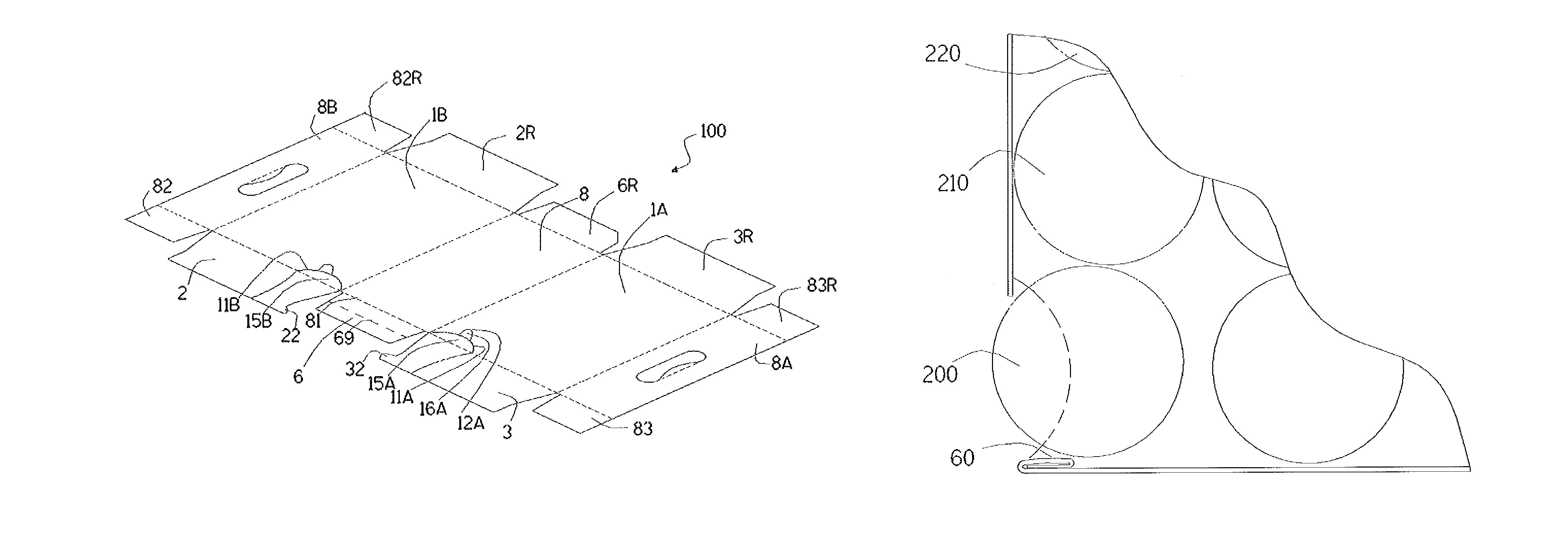
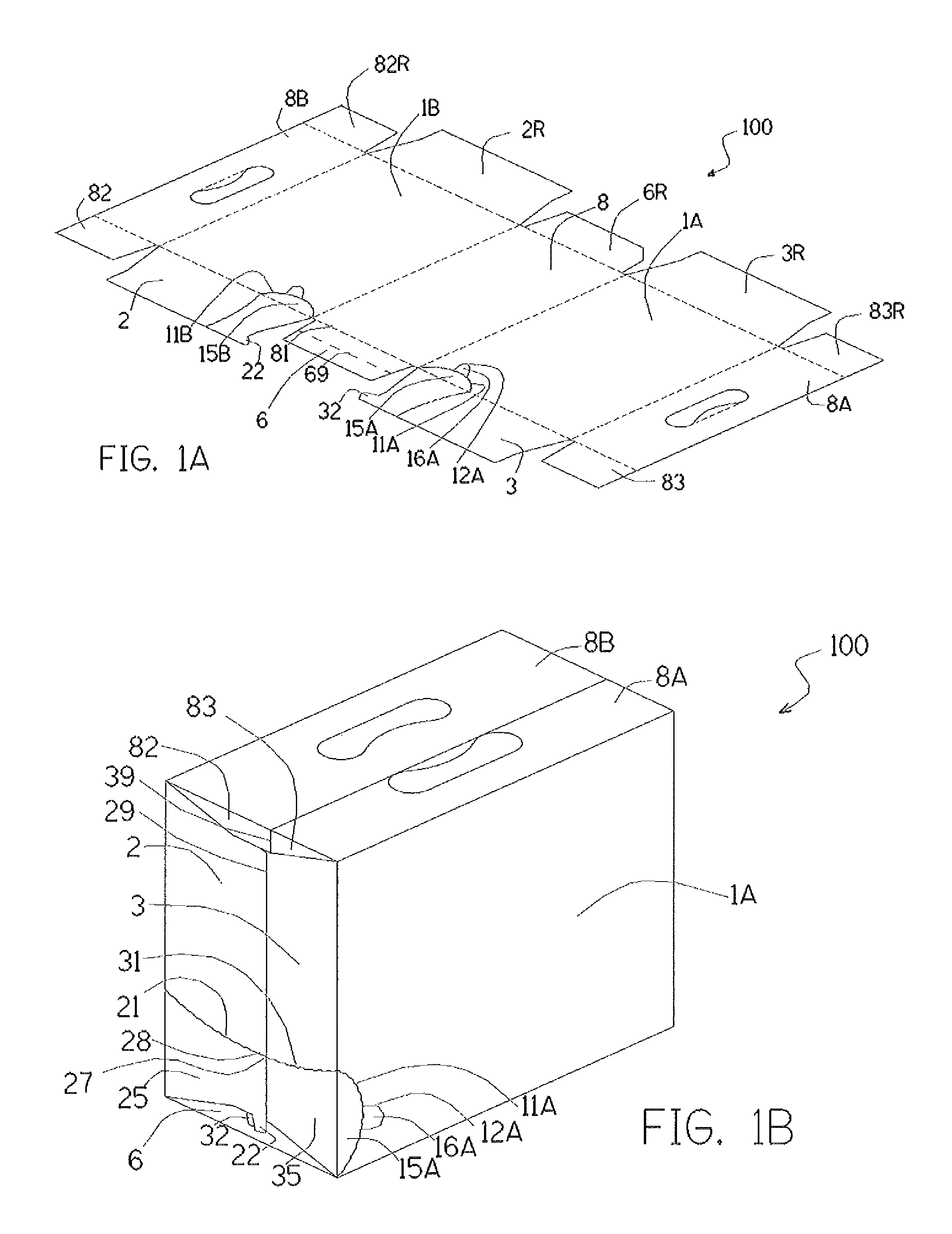
[0056]FIG. 1A illustrates components of the present invention as a blank for a 12-pack one-piece carton 100. FIG. 1B illustrates components of the present invention as the 12-pack carton 100 assembled into a hollow carton and filled with storage cans of a beverage or the like (not shown). A right side panel 1A is hingedly attached to a lower panel 8 (not shown in FIG. 1B), as is a left side panel 1B (not shown in FIG. 1B). The upper structure is made from an upper right flap 8A and an upper left flap 8B.

[0057]The rear end closure structure i...


PUM


Abstract

A dispensing carton and method for dispensing beverage cans is disclosed. The carton enables end-users to easily remove cans from the carton without the common problem of additional cans inadvertently falling out. After removing tear outs, the dispenser flap is folded upon itself and then onto the lower panel to keep cans from rolling out. Optional locking tabs can be used to keep the flap folded. Optional thumb grips and added slits can make tear out removal easier and less trouble prone. The new carton uses existing size carton blanks and requires no added components and no added cost for materials or labor. Furthermore, no changes to manufacturing equipment or manufacturing processes in making carton blanks, assembling the cartons, filling the cartons or transporting the filled cartons are needed.

Description

FIELD OF THE INVENTION[0001]The present invention relates to cartons that package multiple cans of beverages and that incorporate tear out panels to permit dispensing of one can at a time.BACKGROUND OF THE INVENTION[0002]Cartons that package multiple cans of beverages, such as 12-pack beer cartons, and that incorporate tear out panels to permit dispensing of one can at a time are well known. The common problem of gravity causing multiple cans to fall through the dispensing opening is also well known. Prior art shows a number of attempts to solve this problem. The field is crowded due to the sizeable impact an improved carton can have on the multibillion dollar canned beverage market. For example, the introduction of the 6×2 12-pack initially labeled the FridgePack was reported by the Wall Street Journal to have increased sales of Coca-Cola's canned sodas by 10% and now the majority of soda 12-packs are 6×2.[0003]U.S. Pat. No. 3,894,681 to Arneson et al. (Jul. 15, 1975) and assigned ...

Claims


Application Information

Patent Timeline
Patent Type & Authority Patents(United States)
IPC IPC(8): B65D5/72B65D17/28
CPCB65D5/725
Inventor PFANSTIEHL, JOHN
Owner PFANSTIEHL JOHN
Why Eureka
Try Eureka