
Recording apparatus

a recording head and recording head technology, applied in the field of recording head, can solve the problems of troublesome or awkward manual cleaning, contamination of the ejection surface of the recording head, and the inability to completely remove the contamination on the test print area, and achieve the effect of convenient manual cleaning

Active Publication Date: 2012-10-16
BROTHER KOGYO KK
View PDF26 Cites 8 Cited by
  • Summary
  • Abstract
  • Description
  • Claims
  • Application Information

AI Technical Summary

Benefits of technology

[0007]This invention has been developed in view of the above-described situations, and it is an object of the invention, therefore, to provide a recording apparatus which facilitates a manual cleansing of a liquid-droplet ejection area by a user, while preventing contact between a hand of the user and a recording head.
[0009]According to the recording apparatus, when the liquid-droplet ejection area is to be manually cleansed, the liquid-droplet ejection area is located at the cleansing position where the liquid-droplet ejection area is not opposed to the ejection surface of the recording head. This facilitates the manual cleansing, and inhibits a user from inadvertently contacting the recording head during the manual cleansing.

Problems solved by technology

However, it is difficult to completely remove the contamination on the test print area by the belt cleaning mechanism only, and sometimes it is necessary to implement a manual cleansing of the test print area by a user or an operator.
Since the feeder belt and the recording head are disposed close to each other in the inkjet printer, the manual cleansing is troublesome or awkward.
Further, a hand of the operator may contact the recording head during the manual cleansing, which leads to contamination of the ejection surface of the recording head or displacement of the recording head.

Method used


Image

  • Recording apparatus
  • Recording apparatus
  • Recording apparatus

Examples


Embodiment Construction

[0017]Hereinafter, there will be described an inkjet printer as one presently preferred embodiment of the invention, by referring to the accompanying drawings.

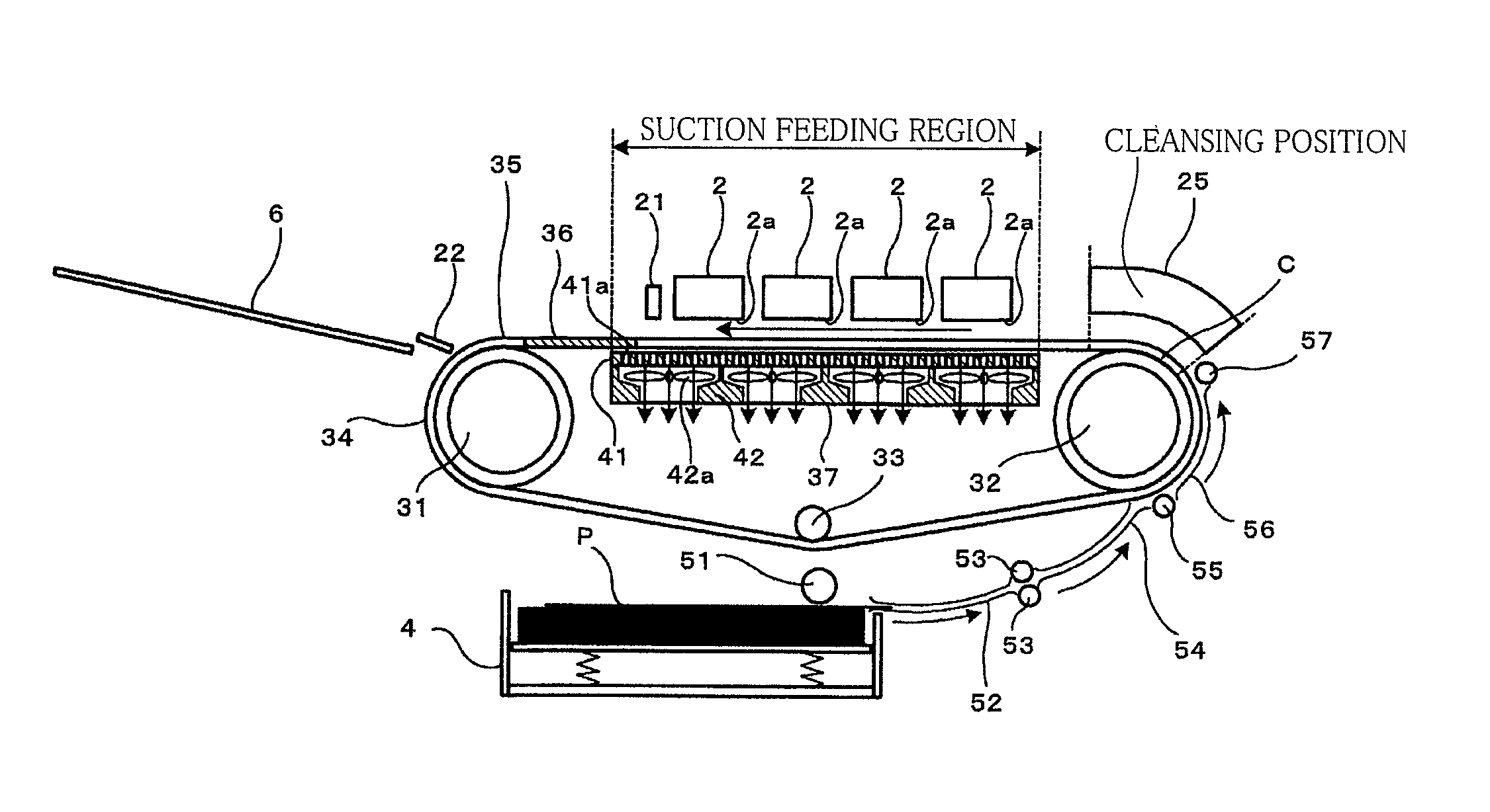
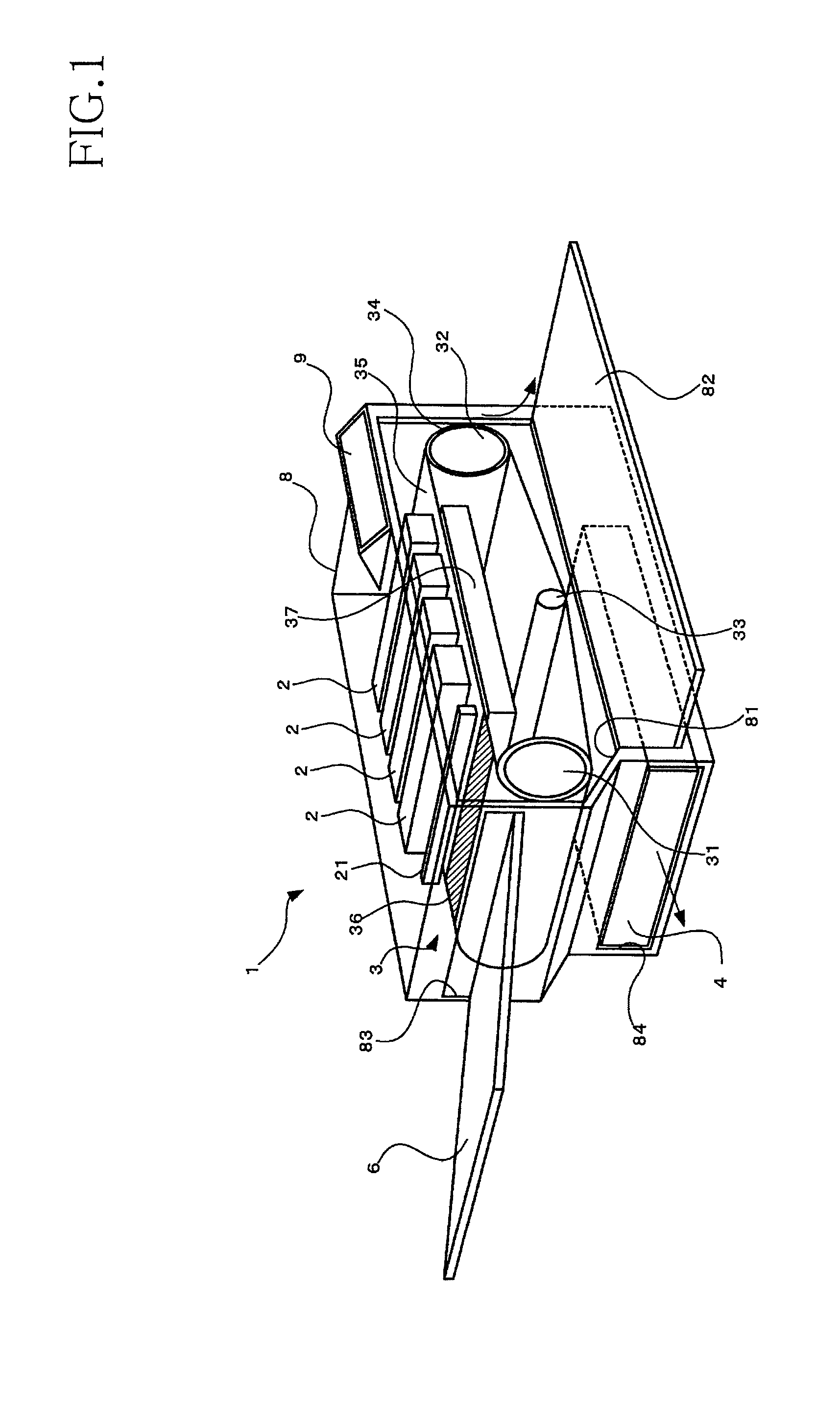
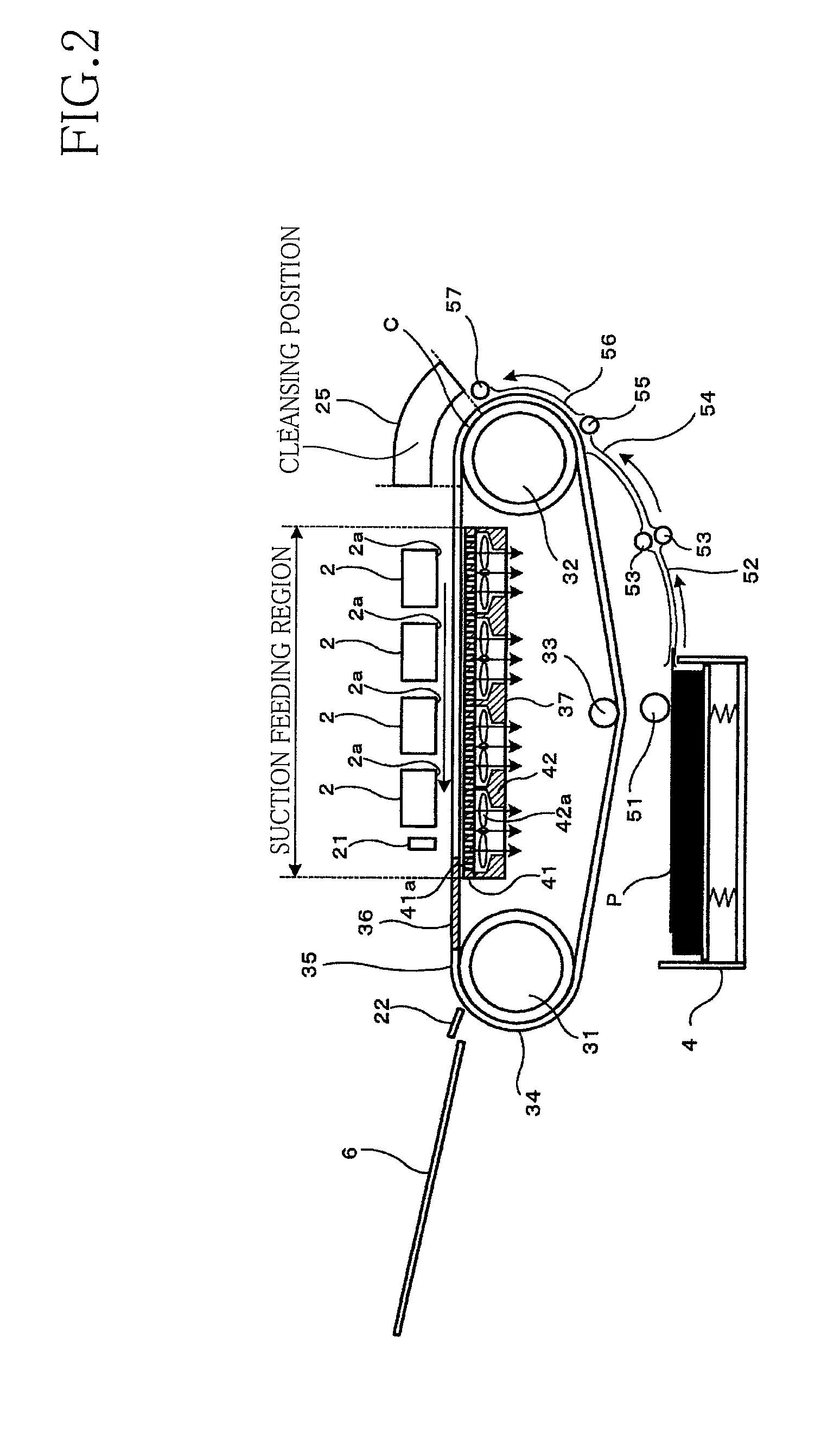
[0018]Referring first to FIG. 1, which shows a general structure of the inkjet printer, reference numeral 1 denotes the inkjet printer. The inkjet printer 1 has a housing 8, which is not transparent but is represented as if transparent in FIG. 1 in order to show an internal structure of the inkjet printer 1. FIG. 2 shows the internal structure of the inkjet printer 1.

[0019]As shown in FIGS. 1 and 2, the inkjet printer 1 is a color inkjet printer including four inkjet recording heads 2. The inkjet printer 1 further includes a sheet supply cassette 4, a feeding mechanism 3, a catch tray 6, the housing 8 accommodating the feeding mechanism 3 and the sheet supply cassette 4, and a control unit 7 (shown in FIG. 4) for controlling operations of the inkjet printer 1. In the housing 8, the recording heads 2, the feeding mechanism 3, a...


PUM


Abstract

There is disclosed a recording apparatus including a recording head, a feeding mechanism, a detector, and a controller. The recording head has an ejection surface from which a droplet of a liquid is ejected. The feeding mechanism includes a plurality of rollers and an endless feeder belt wound around the rollers and having a feeding surface opposed to the ejection surface, and feeds a recording medium placed on the feeding surface a part of which serves as a liquid-droplet ejection area onto which a droplet of the liquid is ejected. The detector detects a trigger for initiating a manual cleansing of the liquid-droplet ejection area. The controller controls the feeding mechanism such that when the detector detects the trigger, the liquid-droplet ejection area is located at a cleansing position where the liquid-droplet ejection area is not opposed to the ejection surface of the recording head.

Description

CROSS REFERENCE TO RELATED APPLICATION[0001]The present application claims priority from Japanese Patent Application No. 2008-223398, which was filed on Sep. 1, 2008, the disclosure of which is herein incorporated by reference in its entirety.BACKGROUND OF THE INVENTION[0002]1. Field of the Invention[0003]The present invention relates to a recording apparatus which ejects a liquid droplet onto a recording medium so as to record an image thereon.[0004]2. Description of Related Art[0005]As an inkjet printer which records an image on a recording sheet as a recording medium by ejecting ink droplets onto the recording sheet, there is known one including a feeding mechanism and an inkjet recording head. The feeding mechanism includes a plurality of rollers and an endless feeder belt wound around the rollers. The recording head has an ejection surface in which a plurality of nozzles open so that ink droplets are ejected therefrom onto the recording sheet placed on an outer circumferential ...

Claims


Application Information

Patent Timeline
Patent Type & Authority Patents(United States)
IPC IPC(8): B41J2/165
CPCB41J11/007B41J11/0085
Inventor ITO, KOJI
Owner BROTHER KOGYO KK
Learn More