Optical beam scanning apparatus and digital writing apparatus

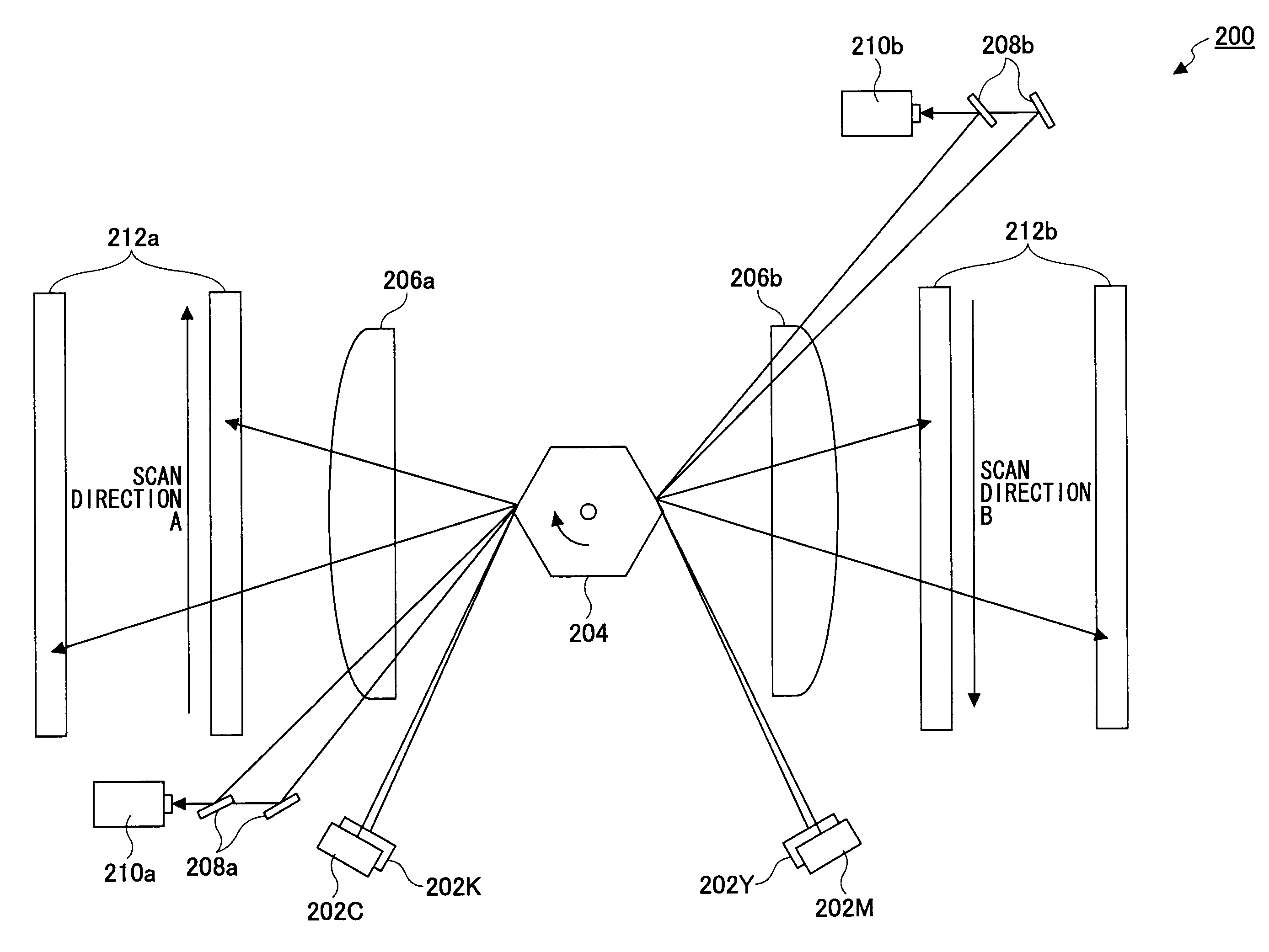
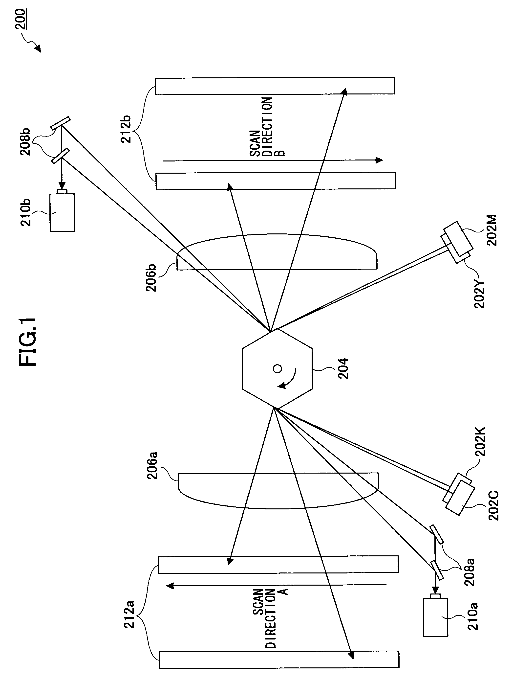
a scanning apparatus and scanning technology, applied in the field of optical beam scanning apparatus, can solve the problems of synchronization detection sensors b>210/b> and b>210/b>, and the conventional configuration is not suitable for reducing space and costs

Inactive Publication Date: 2012-10-16
RICOH KK
View PDF4 Cites 0 Cited by
  • Summary
  • Abstract
  • Description
  • Claims
  • Application Information

AI Technical Summary

Problems solved by technology

Also, the synchronization detection sensors 210a and 210b and optical elements are costly.
In addition, the conventional configuration is not suitable for reducing the spaces and costs.

Method used


Image

  • Optical beam scanning apparatus and digital writing apparatus
  • Optical beam scanning apparatus and digital writing apparatus
  • Optical beam scanning apparatus and digital writing apparatus

Examples


Embodiment Construction

[0022]In the following, the present invention will be described in the embodiment but is not limited to the following embodiment. In the following embodiment, as one example of an optical beam scanning apparatus, a case of using an optical writing apparatus implemented in a laser printer will be illustrated.

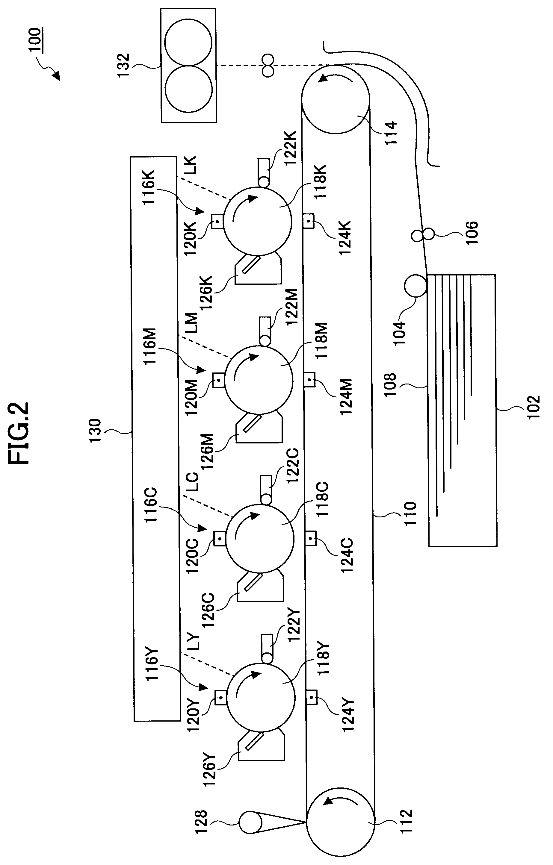
[0023]FIG. 2 illustrates a laser printer according to an embodiment of the present invention. A laser printer 100 illustrated in FIG. 2 includes a paper supply part which includes a paper supply tray 102, a paper supply roller 104, and a separation roller 106, an optical writing apparatus 130 which includes optical elements such as a laser diodes, a polygon mirror, lenses, and alike, image formation parts 116K, 116M, 116C, and 116Y which include corresponding photosensitive drums 118K, 118M, 118C, and 118Y, electrification devices 120K, 120M, 120C, and 120Y, development devices 122K, 122M, 122C, and 122Y, transfer devices 124K, 124M, 124C, and 124Y, static eliminating devices 126...


PUM


Abstract

An optical beam scanning apparatus is disclosed, including: a laser source that emits an optical beam, a deflection part that deflects the optical beam, a light receiving part that receives a returning light of the optical beam which is deflected toward the laser source by the deflection part, a signal generation part that generates a synchronization detection signal, and an optical source drive part that conducts a lighting control of the laser source. The light receiving part is arranged in vicinity to the laser source. The signal generation part detects a timing at which the light receiving part receives the returning light, by an output signal from the light receiving part to generate the synchronization detection signal. The optical source drive part conducts the lighting control of the laser source in response to the synchronization detection signal as a reference.

Description

BACKGROUND OF THE INVENTION[0001]1. Field of the Invention[0002]The present invention is related to an optical beam scanning apparatus, and more particularly to the optical beam scanning apparatus and a digital writing apparatus, which are mounted in an image forming apparatus implementing an optical beam scan method and perform image writing.[0003]2. Description of the Related Art[0004]An image forming apparatus such as a digital composition apparatus and a laser printer for conducting an image form in an optical beam scan method includes an optical beam scanning apparatus for controlling a laser diode to turn on and for deflecting an optical beam emitted from the laser diode by using a polygon mirror which is rotating to scan in the main scan direction, in order to write an image for each of main scan lines on a photosensitive drum.[0005]In the above-described optical beam scanning apparatus, for example, as disclosed in Japanese Laid-open Patent Application No. 2003-29181, in ord...

Claims


Application Information

Patent Timeline
Patent Type & Authority Patents(United States)
IPC IPC(8): H04N1/04B41J2/435B41J2/455B41J2/47G03G13/04G03G21/14G01D15/06G01D15/16
CPCB41J2/473G02B26/123G02B26/127H04N1/053H04N1/1135H04N1/12H04N2201/0082H04N2201/04713H04N2201/04786H04N2201/04732H04N2201/04744
Inventor KOMAI, KUNIHIRO
Owner RICOH KK
Why Eureka
Try Eureka