Glass film laminate, glass roll of the laminate, method of protecting end face of glass film, and method of producing glass roll

a technology of glass film and end face, which is applied in the direction of glass making apparatus, manufacturing tools, transportation and packaging, etc., can solve the problems of brittle glass used in the substrate, low flexibility, and tensile stress, and achieve the effect of preventing stress, improving the handleability of glass film, and convenient production-related treatmen

Active Publication Date: 2012-11-06
NIPPON ELECTRIC GLASS CO LTD
View PDF12 Cites 3 Cited by
  • Summary
  • Abstract
  • Description
  • Claims
  • Application Information

AI Technical Summary

Benefits of technology

[0020]According to the invention of the first aspect, the glass film laminate has the glass film, the support sheet laminated on one surface of the glass film to extend off the glass film, and the protective sheet peelably laminated on the other surface of the glass film to cover the edges of the glass film, and hence the edges of the glass film can be protected by being sandwiched between the support sheet and the protective sheet. As a result, a stress can be prevented from converging on an edge of the glass film, and hence the occurrence of breaking, chipping, or the like in the glass film with a fine flaw or the like remaining on an end face of the glass film as an origin can be effectively prevented. Accordingly, the handleability of the glass film can be improved.
[0021]According to the invention of the second aspect, the glass film has a thickness of 300 μm or less, and hence production-related treatments can be easily performed even in an ultrathin glass film which is additionally hard to handle and which is apt to cause a problem such as breaking or chipping.
[0022]According to the invention of the third aspect, the support sheet has a cohesive strength of 0.002 to 2.00 N / 25 mm, and hence the support sheet is weakly cohesive. Accordingly, the support sheet can be easily peeled from the glass film after the protective sheet has been peeled. As a result, the support sheet can be easily peeled from the glass film laminate after production-related treatments, and hence only the glass film can be easily incorporated into each of various devices and the like.
[0023]According to the invention of the fourth aspect, the support sheet has a thickness of 3 to 250 μm, and hence the glass film can be surely supported.
[0024]According to the invention of the fifth aspect, the protective sheet has a thickness of 3 to 250 μm, and hence the glass film and the support sheet can be appropriately protected.
[0025]According to the invention of the sixth aspect, the protective sheet covers the cohesive portion of the support sheet, and hence the adhesion of dirt or the like to the cohesive portion of the support sheet and the cohesion of the support sheet upon handling of the glass film can be prevented.

Problems solved by technology

However, glass used in the substrate is brittle to a tensile stress unlike a resin film, and hence has low flexibility.
The concentration of a tensile strength to the surface of the glass substrate by the bending of the glass substrate leads to the breakage of the substrate.
However, when the glass substrate used in those electronic devices is turned into a film, some degree of a change in stress leads to the breakage of the film because glass is a brittle material.
Accordingly, there arises such a problem that it is remarkably difficult to handle the film upon performance of the above various treatments related to the production of the electronic devices.
However, upon handling of the laminate described in Patent Document 2, such a problem that a crack generates from an edge of the glass film and hence breaking, chipping, or the like occurs arises.
An unnecessary portion generated during the forming of the glass film is cut and removed, and hence a fine flaw upon cut and removal of the unnecessary portion remains at the edge of the glass film.

Method used


Image

  • Glass film laminate, glass roll of the laminate, method of protecting end face of glass film, and method of producing glass roll
  • Glass film laminate, glass roll of the laminate, method of protecting end face of glass film, and method of producing glass roll
  • Glass film laminate, glass roll of the laminate, method of protecting end face of glass film, and method of producing glass roll

Examples


Embodiment Construction

[0037]Hereinafter, preferred embodiments of a glass film laminate and a glass roll of the glass film laminate according to the present invention are described with reference to the drawings.

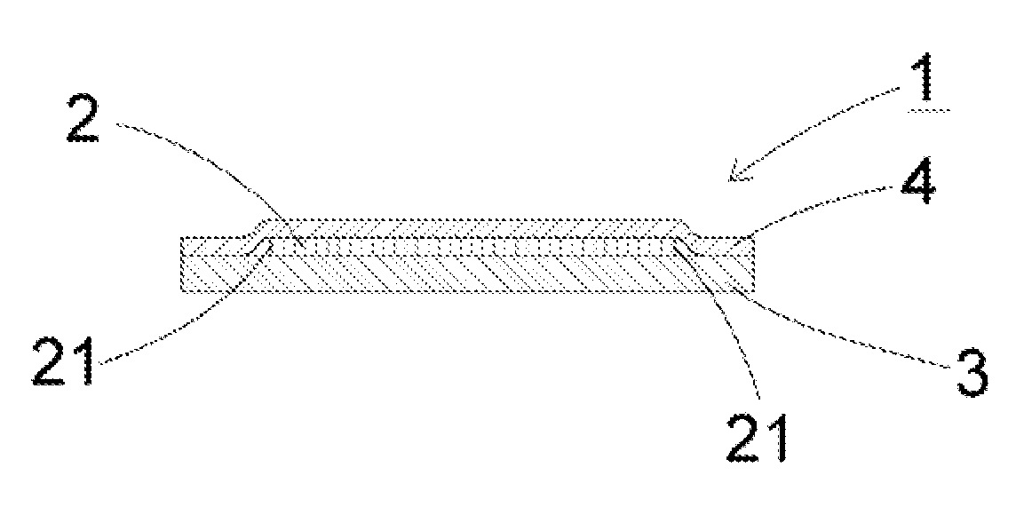
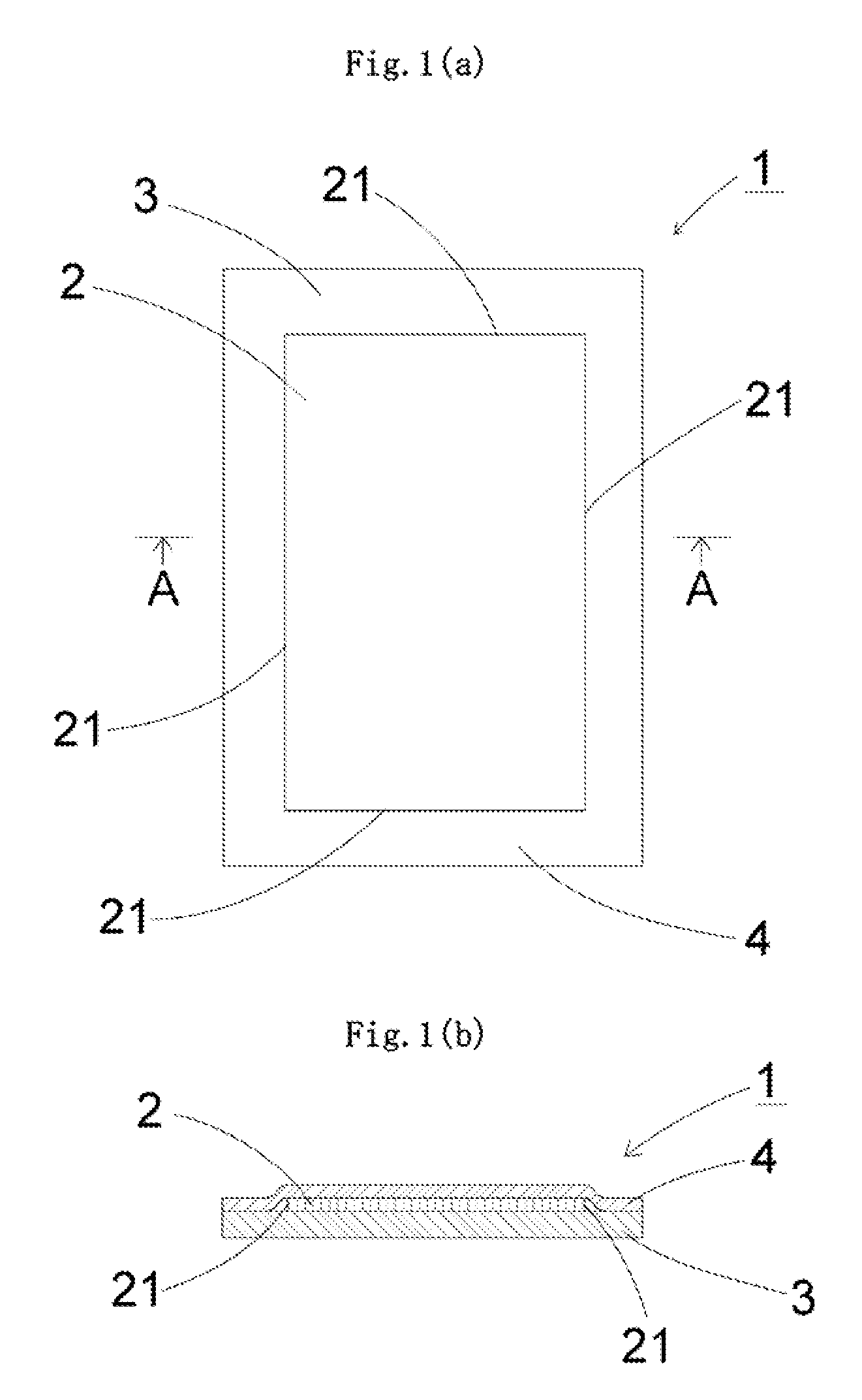
[0038]As illustrated in each of FIGS. 1a) and 1(b), a glass film laminate (1) according to the present invention has a glass film (2), a support glass (3), and a protective film (4).

[0039]A silicate glass, preferably a silica glass or a borosilicate glass, or most preferably a no-alkali borosilicate glass is used in the glass film (2). When the glass film (2) contains an alkali component, the substitution of a cation occurs on its surface. As a result, the so-called soda blasting phenomenon occurs, and hence the film becomes structurally rough. In this case, when the glass film (2) is used while being curved, the film may break from a portion that has become rough owing to age deterioration. It should be noted that the term “no-alkali borosilicate glass” as used herein refers to a glass substanti...


PUM

PropertyMeasurementUnit
thicknessaaaaaaaaaa
thicknessaaaaaaaaaa
thicknessaaaaaaaaaa

Abstract

A glass film laminate has a glass film, a support sheet laminated on one surface of the glass film to extend off the glass film, and a protective sheet peelably laminated on the other surface of the glass film to cover the edges of the glass film. A glass roll is produced by winding the laminate.

Description

TECHNICAL FIELD[0001]The present invention relates to a glass film laminate in which a glass substrate for a device such as a glass substrate used in a flat panel display, for example, a liquid crystal display or an OLED display, or a glass substrate for a solar cell and a glass film used in, for example, a cover glass for an OLED lighting are supported by a support sheet, a glass roll of the laminate, a method of protecting an end face of a glass film, and a method of producing a glass roll.BACKGROUND ART[0002]From the viewpoint of space savings, flat panel displays such as liquid crystal displays, plasma displays, OLED displays, and field emission displays have recently become widespread instead of CRT displays that have been conventionally widespread. An additional thinning has been required for each of those flat panel displays. In particular, the OLED displays have been required not only to be easily portable by being folded or rolled but also to be usable in curved surfaces as...

Claims


Application Information

Patent Timeline
Patent Type & Authority Patents(United States)
IPC IPC(8): B32B17/06B32B7/10
CPCB32B7/06C03B17/064B32B17/064Y10T428/24752Y10T428/239B32B17/10C03B17/06B32B7/12
Inventor NAKAMURA, TAKAHIDEMORI, KOICHI
Owner NIPPON ELECTRIC GLASS CO LTD
Why Eureka
Try Eureka