
Loupe support system

a support system and loupe technology, applied in the field of loupe support systems, can solve the problems of inability to mount the light, inability to light up long and small drillings, and inability to light up shadowless drillings such as root canal drillings, and achieve the effect of simple and lasting adjustment of loupe oculars

Inactive Publication Date: 2012-11-06
HEINE OPTOTECHN
View PDF8 Cites 10 Cited by
  • Summary
  • Abstract
  • Description
  • Claims
  • Application Information

AI Technical Summary

Benefits of technology

[0007]The object of the invention is to create a loupe support system enabling simple and lasting adjustment of loupe oculars and light as well as shadowless lighting.
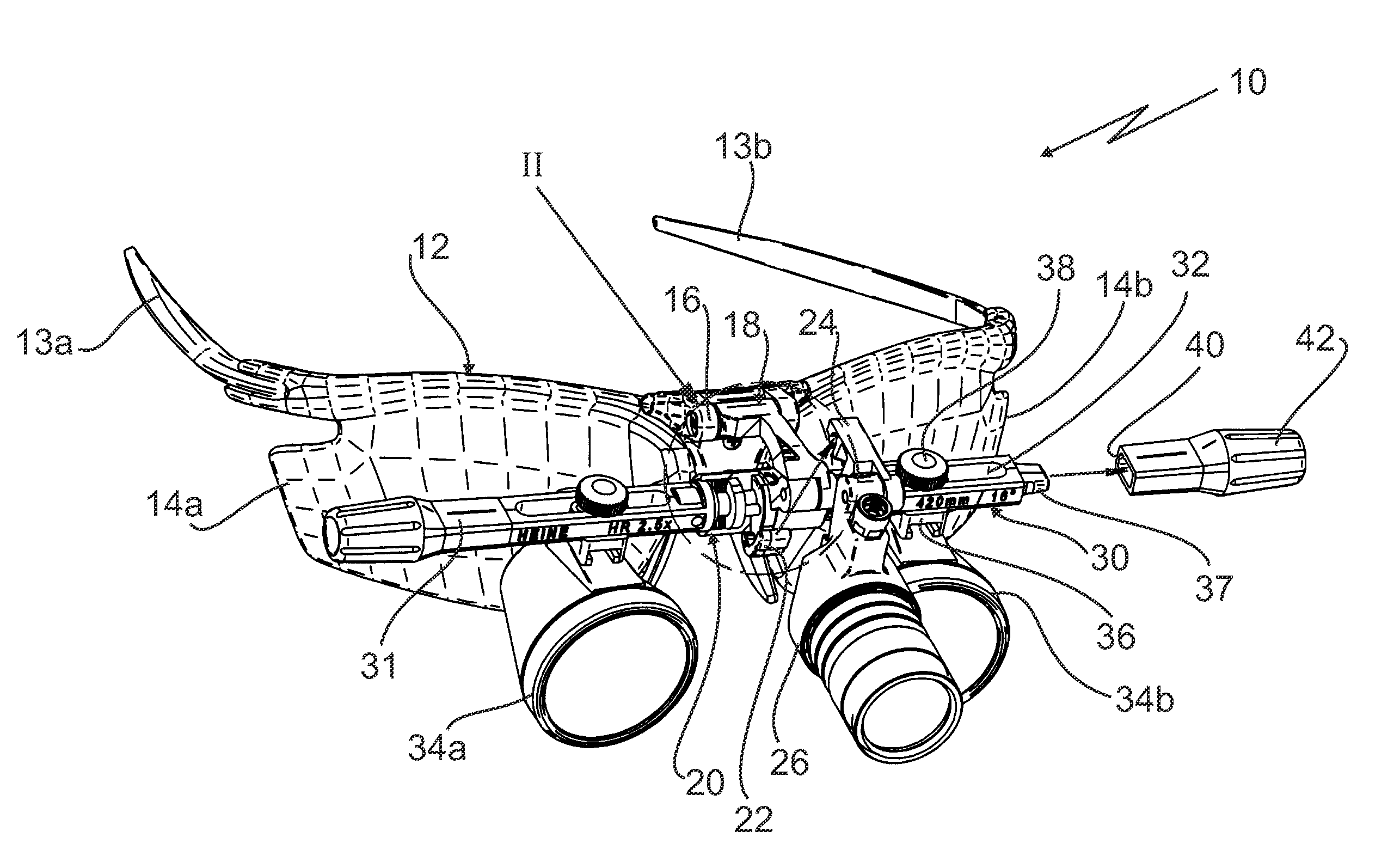
[0009]In the loupe support system according to the present invention the light mounting element is supported such that it can rotate about a rotary axis being coaxial with respect to the rotary axis of the support element. This makes it possible to arrange the loupe oculars and a light such that their optical axes lie in one plane, whereby shadowless lighting even of small drillings is possible. The light and the loupe ocular may be pivoted together or separately from one another.
[0010]In order to make sure that the loupe support system and the light remain in their respective rotary position, it is advantageous to provide a clamping device.
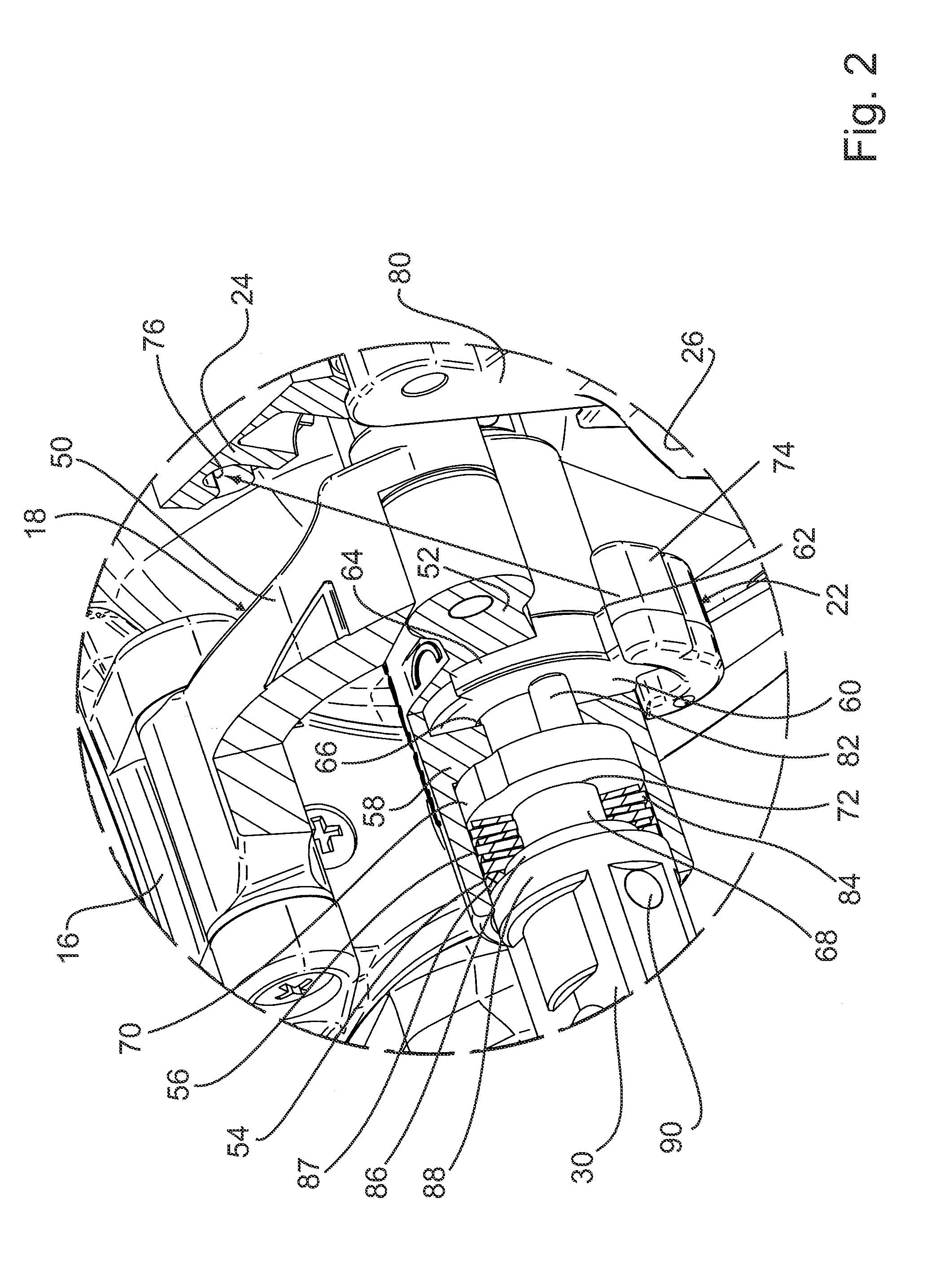
[0014]For good sealing between the sleeve portion and the support portions, the end of each support portion extending into the cylindrical space is preferably formed by a cylindrical portion which is adjoined by a cylindrical collar, the outer diameter of which is larger than the outer diameter of the cylindrical portion and corresponds to the inner diameter of the cylindrical space. At the cylindrical portion there is arranged a ring seal engaging the cylindrical portion and the inner wall of the cylindrical space.
[0016]For optimal illumination, a light can be mounted at the light mounting element such that the optical axis of the light lies in the plane of the optical axes of the loupe oculars. The convergence of the loupe oculars is preferably adjusted such that the three optical axes intersect at an optimal distance in front of a user's eye amounting to about 200 to 600 mm. Thereby the field of view can be optimally illuminated so that shadowless lighting even of long narrow drillings is possible.

Problems solved by technology

In the case of the known loupe support system it is not possible to mount the light and the loupe oculars on a congruent illumination axis.
For this reason, shadowless lighting of long and small drillings, such as root canal drillings, is not possible.

Method used


Image

  • Loupe support system
  • Loupe support system
  • Loupe support system

Examples


Embodiment Construction

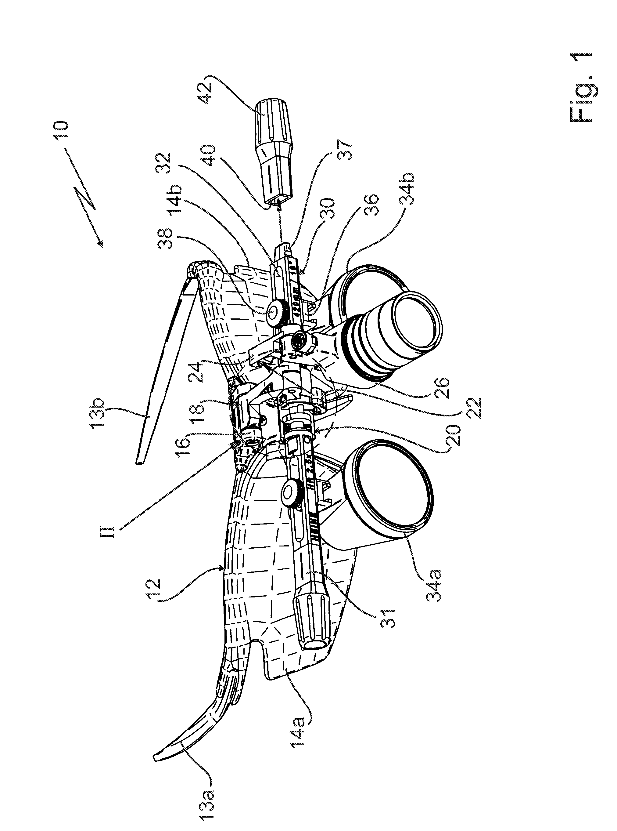
[0028]The loupe support system 10 shown in FIG. 1 comprises an eyeglass frame 12 having two temples 13a, 13b and two eyeglasses 14a, 14b connected through a bridge 16. At the bridge 16 there is mounted a holding device 18 having a pivoting bracket 50, one end of which is articulated at the bridge 16 pivotably about a horizontal axis. At the other end of the pivoting bracket 50 there is a connecting arm 52 articulated also in a rotatable manner about a parallel horizontal axis. A sleeve portion 54 is mounted at the end of the connecting arm 52 opposite the hinge point, the longitudinal center line of the sleeve portion 54 being parallel to both of the pivoting axes. In the sleeve portion 54 a support element is supported such that it can rotate about the longitudinal center axis of the sleeve portion 54, the support portion comprising of a left support portion 31 and a right support portion 30 as well as an axle 68 extending centrally through the sleeve portion 54 and connecting the ...


PUM


Abstract

A loupe support system includes a frame (12) which can be mounted at the head of a user and at which a holding device (18) is mounted, an elongated support element (30, 31, 68) which, at its central region, is supported at the holding device (18) such that it can rotate about its longitudinal central axis, wherein a respective loupe ocular (34) is mounted at the support element (30, 31, 68) on each of both sides of the holding device, and a light mounting element (22) supported at the holding device (18) such that it can rotate about a rotary axis being coaxial with respect to the longitudinal central axis of the support element (30, 31, 68).

Description

CROSS-REFERENCE TO RELATED APPLICATION[0001]This application claims benefit of German Patent Application 10 2009 023 049. 1, filed May 28, 2009, the disclosure of which is incorporated herein in its entirety by reference.BACKGROUND OF THE INVENTION[0002]1. Field of the Invention[0003]The invention relates to a loupe support system comprising a frame which can be mounted at the head of a user and at which one end of a holding device is mounted, and an elongated support element which, at its central region, is supported at the holding device such that it can rotate about its longitudinal central axis, wherein a respective loupe ocular is mounted at the support element on each of both sides of the holding device, and a light mounting element at which a light can be mounted and which is supported at the holding device such that it can rotate.[0004]2. Description of the Background Art[0005]A loupe support system of this kind is known from WO 03 / 007048 A2. In the case of this loupe suppor...

Claims


Application Information

Patent Timeline
Patent Type & Authority Patents(United States)
IPC IPC(8): G02B25/00
CPCG02B25/002G02C7/08G02C9/00
Inventor HEINE, OLIVERRAAB, ROMANGUEGEL, GERHARDKNESEWITSCH, STEFANSCHNEIDER, ANTON
Owner HEINE OPTOTECHN
Learn More