Method for forming optically encoded thin films and particles with grey scale spectra

a grey scale spectra and optical encoder technology, applied in the field of encoding, can solve the problems of slow diffusion rate of labeling/encoding itself, difficult to obtain number, and limit the concentration range of analytes being sensed in positional arrays

Active Publication Date: 2012-11-13
RGT UNIV OF CALIFORNIA
View PDF31 Cites 0 Cited by
  • Summary
  • Abstract
  • Description
  • Claims
  • Application Information

AI Technical Summary

Benefits of technology

[0026]The use of encoded silicon particles of the invention in medical diagnostic applications has advantages over organic dyes or quantum dots. In vivo studies have shown the biocompatibility of porous silicon, as well as the long-term stability of reflectance data from multilayer structures. Additionally, the possibility of optically addressing particles at near-infrared, tissue-penetrating wavelengths without the losses associated with low fluorescence quantum yields makes these materials amenable to in vivo diagnostics. Finally, because the porous codes are an integral and orderly part of the porous structure, it is not possible for part of the code to be lost, scrambled or photobleached, as can occur with quantum dots or fluorescent molecules.

Problems solved by technology

At the microscale, however, labeling / encoding itself becomes difficult.
Positional arrays, however, can suffer from slow diffusion rates and limits on the concentration ranges of analytes being sensed.
In practice, this number is difficult to obtain because of spectral overlap and sample inhomogeneities.
Also, despite the increased photostability of quantum dots, fluorescence quenching is still possible, casting uncertainty on using relative intensity measurements as a reliable encoding method.
Deposition of rods is a relatively complex process, however, and may be difficult to apply as an encoding strategy where, for example, a large number of codes is desirable because each rod must be brought into focus in an optical reader (such as a microscope) in order to read out the codes.

Method used


Image

  • Method for forming optically encoded thin films and particles with grey scale spectra
  • Method for forming optically encoded thin films and particles with grey scale spectra
  • Method for forming optically encoded thin films and particles with grey scale spectra

Examples


Embodiment Construction

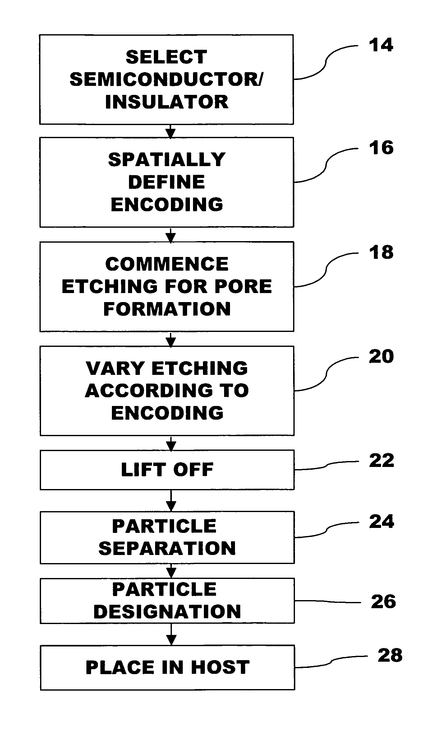
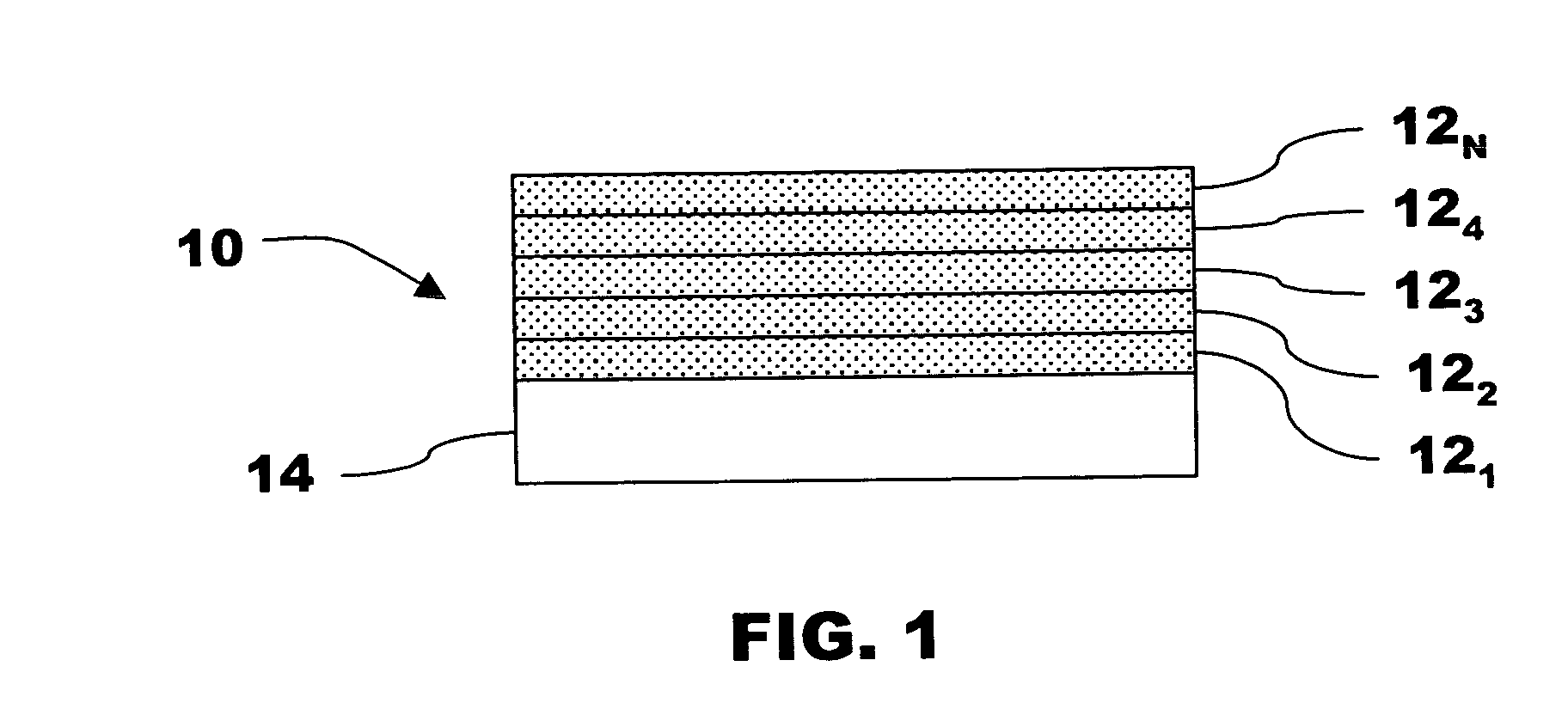
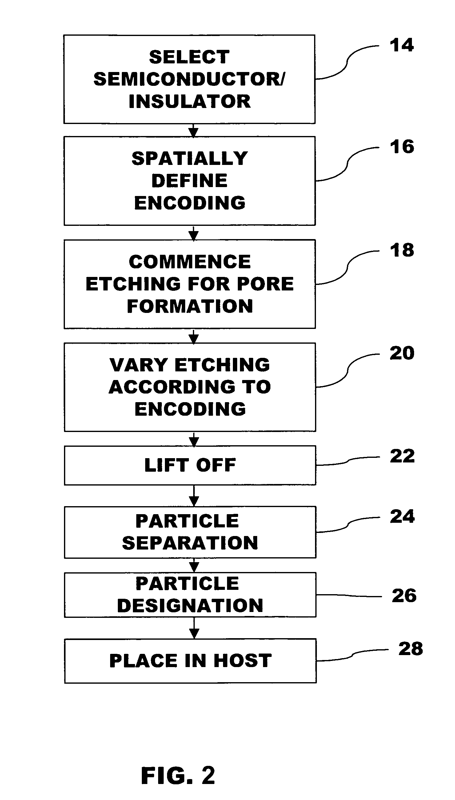
[0011]The invention concerns a particle having a grey scale code embedded in its physical structure by refractive index changes between different regions of the particle. A change in the refractive index is preferably obtained by varying porosity formed in the particle. Reflections taken from the particles produce an optical signature, in the visible and / or non-visible wavelengths. In preferred embodiments, the number of peaks, their locations, and intensities can be used to produce a high number of unique optical signatures exhibiting grey scale codes. In preferred embodiment formation methods, a porous encoded structure is produced by an etching process during which the etching conditions are varied during pore formation according to a computer generated waveform designed to produce a grey scale coding. A dicing may be conducted to form individual encoded particles having a range of small sizes, e.g., from hundreds of nanometers to hundreds of microns.

[0012]Methods and particles o...


PUM

PropertyMeasurementUnit
porosityaaaaaaaaaa
frequencyaaaaaaaaaa
reflectivityaaaaaaaaaa

Abstract

The invention concerns a method of making a thin film and / or particle having a grey scale code embedded in its physical structure by refractive index changes between different regions of the thin film or particle, as well as thin films and particles made by the method. In a preferred method for encoding a thin film, a semiconductor or insulator substrate is etched to form a thin film including pores. The etching conditions are controlled to vary porosity in the thin film according to a pattern that will generate an optical signature in the reflectivity spectrum in response to illumination such that the optical signature will including a grey scale code. The etching waveform is formed by the addition of at least two separate sine components in accordance with the following equations (1)An=(Anmax−Anmin) / 2; (2) kn=frequency=1 / period; (3) yn=An[sin(knt−Φ)+1]+Anmin (4) ycomp=[y1+ . . . +yn] / n wherein equation (1) defines the amplitude of sine component n, which results in the spectral peak height, or grey scale of a bit; Equation (2) defines the frequency of the each sine component, which results in the spectral position of a peak, or identification of a bit (1st bit, 2nd bit, etc. . . );. Equation (3) defines sine component n and Equation (4) defines the composite waveform used to drive the electrochemical etch. The film can be removed and diced into particles.

Description

PRIORITY CLAIM[0001]Applicant claims priority benefits under 35 U.S.C. § 119 on the basis of Patent Application No. 60 / 532,144, filed Dec. 22, 2003.STATEMENT OF GOVERNMENT INTEREST[0002]This invention was made with Government assistance under DARPA Grant No. DASG60-03-C-0014. The Government has certain rights in this invention.TECHNICAL FIELD[0003]A field of the invention is encoding. Additional exemplary fields of the invention include the life sciences, security, product marking, food processing, agriculture, and chemical detection.BACKGROUND ART[0004]A well-appreciated need for labeling exists in society. Labeling is a fundamental basis for tracking and identifying. Encoding can be used as a form of labeling understood by persons or equipment, as in the case of bar coding. At the microscale, however, labeling / encoding itself becomes difficult.[0005]Strategies to encode microscale materials have accordingly received increased attention for such uses as high-throughput screening in...

Claims


Application Information

Patent Timeline
Patent Type & Authority Patents(United States)
IPC IPC(8): G06K7/10G06K7/14G01N21/45G01N21/64G01N21/77G01N33/543G01N33/58G06K19/00G06K19/06
CPCB82Y10/00B82Y20/00G01N21/41G01N21/45G01N21/6428G01N33/54373G01N33/587G06K19/06046G01N2021/7773G01N2021/7779G01N2021/7786
Inventor SAILOR, MICHAEL J.MEADE, SHAWN O.
Owner RGT UNIV OF CALIFORNIA
Why Eureka
Try Eureka