Robot system using robot to load and unload workpiece into and from machine tool

a robot and workpiece technology, applied in the field of robot systems, can solve the problems of easy separation of transportation from the molding machine, and easy to become large robots. achieve the effect of simple configuration

Active Publication Date: 2012-11-13
FANUC LTD
View PDF16 Cites 17 Cited by
  • Summary
  • Abstract
  • Description
  • Claims
  • Application Information

AI Technical Summary

Benefits of technology

[0013]Accordingly, an object of the present invention is to provide a robot system for loading and unloading a workpiece into and from a machine tool, which has a new configuration and can secure work space for maintenance etc. of the machine tool at the front of a door of the machine tool through which a workpiece is loaded and unloaded.
[0016]In the above robot system, it is preferable that the second arm member has a base part coupled to the first arm member so as to be rotatable about the third axis, and a shaft part coupled to the base part so as to be rotatable about a fourth axis vertical to the third axis, and that the robot further includes a holding mechanism holding the workpiece, which holding mechanism has a base part coupled to the shaft part of the second arm member so as to be able to swivel about a fifth axis vertical to the fourth axis, and a terminal end attached to the base part so as to be rotatable about a sixth axis vertical to the fifth axis and provided with a holding part for the workpiece. This makes it possible to suitably adjust the posture of the workpiece at the time of loading and unloading into and from the machine tool.
[0017]According to the robot system of the present invention, it is possible to make the robot retract from the front of the door for loading and unloading of workpieces of the machine tool. Due to this, it is possible to secure work space for maintenance etc. of a machine tool. Still further, a robot having a simple configuration can be used to make the front end of the arm member reach a desired position inside the door of the machine tool and suitably load and unload a workpiece into and from the machine tool.

Problems solved by technology

While such a robot has the merit that compared with a swivel arm, complicated coordinate conversion at the time of control becomes unnecessary and the operation is easy to understand, it has the demerits that the robot easily becomes large, in particular the total height easily becomes greater, and transport separate from the molding machine easily become necessary.
At the time of this type of work, if robot 50 were at the front of door 61, the work space would be narrow and work would be difficult.
However, a robot which can be arranged on a machine tool is limited in weight and size and therefore, when handling a large workpiece, it is difficult to use such a configuration.
Further, since it is necessary to make the robot comparatively small, the processing range of the robot also tends to become narrower.
For this reason, there also tend to be limits to the layout of the device for supplying and carrying out the workpieces.
However, in a configuration using one robot for one machine tool, using rails for movement of the robot is considerably costly and not necessarily preferable.

Method used


Image

  • Robot system using robot to load and unload workpiece into and from machine tool
  • Robot system using robot to load and unload workpiece into and from machine tool
  • Robot system using robot to load and unload workpiece into and from machine tool

Examples


Embodiment Construction

[0025]Preferred embodiments of the present invention will be described below with reference to the drawings.

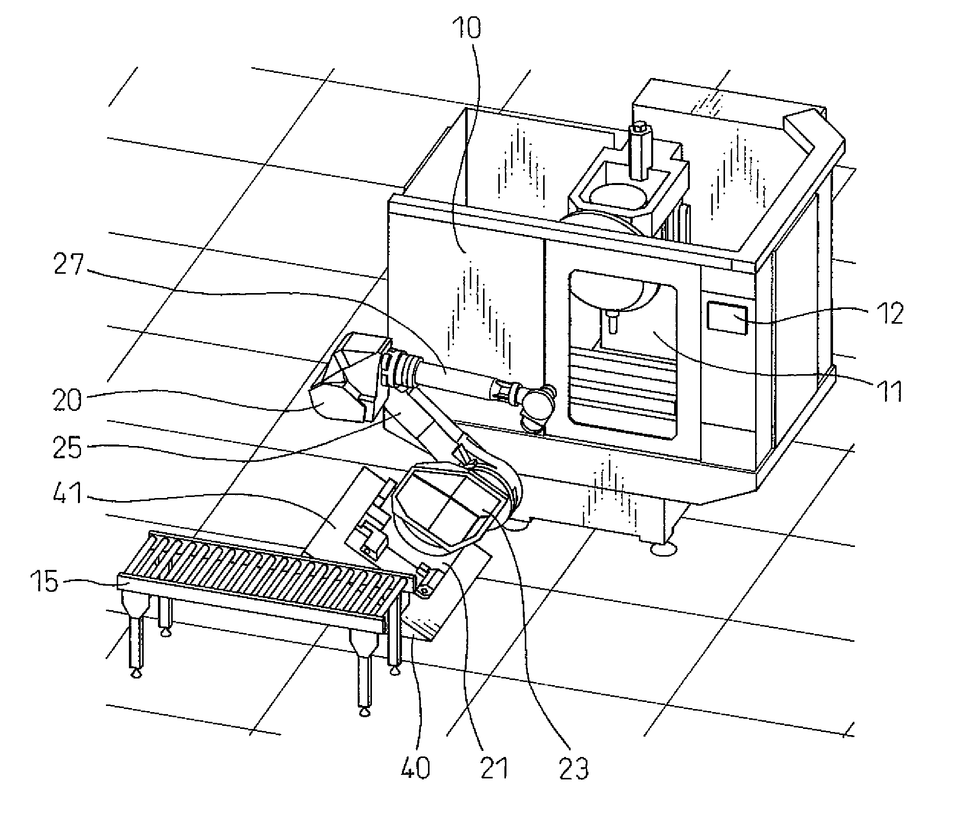
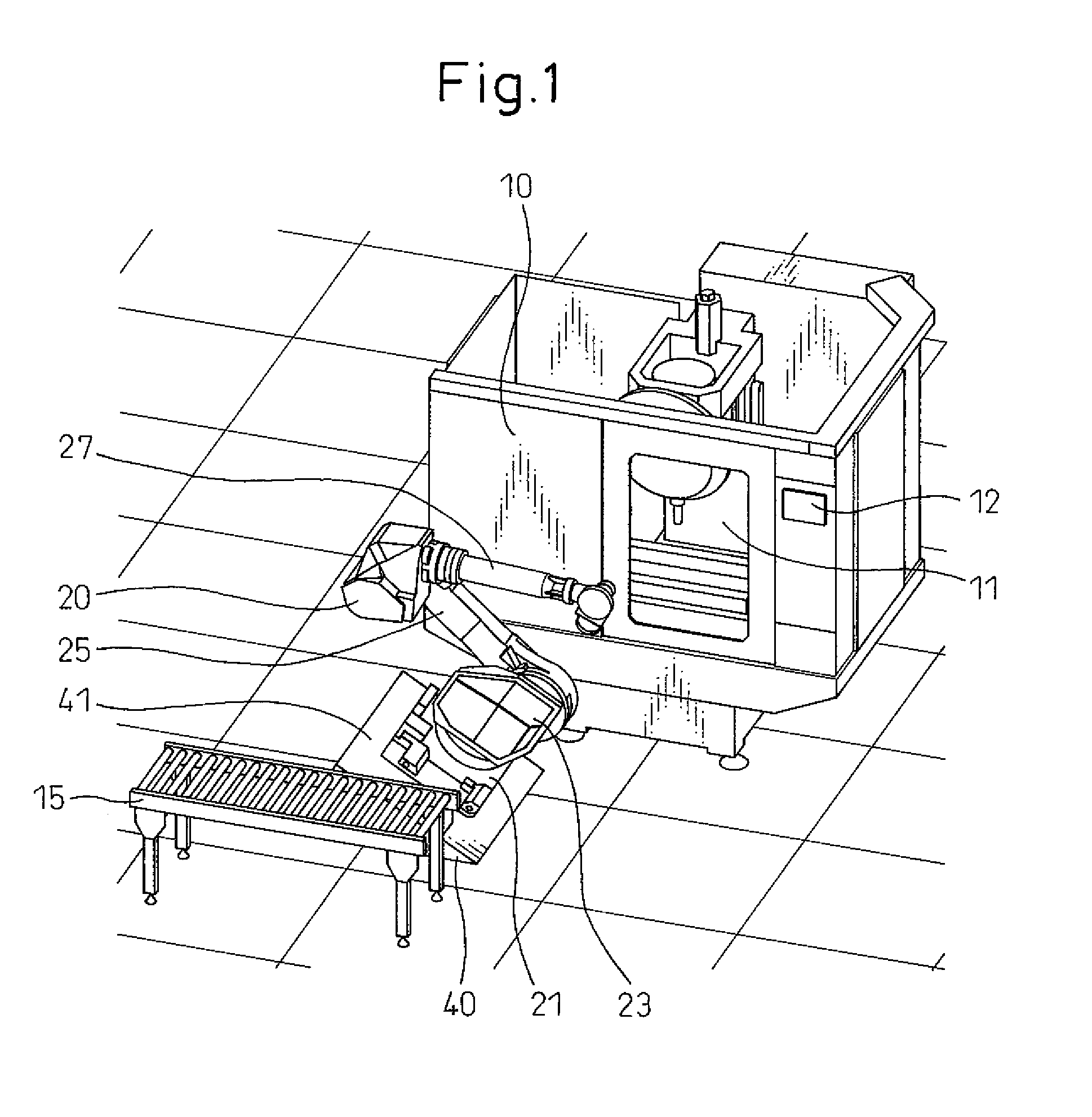
[0026]FIG. 1 is a perspective view schematically showing the overall configuration of a robot system of the present embodiment. As illustrated, the robot system of the present embodiment is configured using one robot 20 for one machine tool 10.

[0027]Machine tool 10 may be a molding machine, machining center, or any other known type of machine for fabricating a molded part as a workpiece or connecting a molded part to, machining, or performing other processing on a supplied workpiece. Since details of machine tool 10 are not directly related to the present invention, an explanation thereof will be omitted. Whatever the case, machine tool 10 has a door 11 through which a not shown workpiece can be loaded and unloaded. Further, near door 11 on the side surface of machine tool 10 where door 11 is provided, an operating panel 12 is disposed. While not shown in detail, inside door 1...


PUM


Abstract

A robot includes a base member, which is installed at a position offset from the front of a door of a machine tool to the side, as viewed in a direction vertical to the surface where the door is provided and is fixed to a surface of a base slanted so as to face the door side. A rotary member is coupled to the base member so as to be rotatable about a first axis extending vertical to the slanted surface. A first arm member is coupled to the rotary member so as to be able to swivel about a second axis vertical to the first axis, and a second arm member is coupled to the first arm member so as to be able to swivel about a third axis parallel to the second axis.

Description

RELATED APPLICATIONS[0001]The present application is based on, and claims priority from, Japanese Application No. 2008-200170, filed Aug. 1, 2008, the disclosure of which is hereby incorporated by reference herein in its entirety.BACKGROUND OF THE INVENTION[0002]1. Field of the Invention[0003]The present invention relates to a robot system using a robot to load and unload (or place and remove) a workpiece into and from a machine tool.[0004]2. Description of the Related Art[0005]Known in the art is a robot system using a robot to mount a workpiece to a predetermined mounting portion of a molding machine or a machining center or other machine tool or remove a workpiece finished being processed from the mounting portion. Using such a robot system, it becomes possible to automate processing of a large number of workpieces by a machine tool.[0006]A robot for loading and unloading a workpiece into and from a machine tool uses a mechanism combining linear movement axes and swivel arms. In ...

Claims


Application Information

Patent Timeline
Patent Type & Authority Patents(United States)
IPC IPC(8): B25J18/00
CPCB25J9/0009B25J9/047
Inventor NIHEI, RYOKINOSHITA, SATOSHI
Owner FANUC LTD
Why Eureka
Try Eureka