Film-forming apparatus

A film-forming device and film-forming chamber technology, applied in gaseous chemical plating, coating, electrical components, etc., can solve the problems of increased work load, limited work space, difficult maintenance work, etc., to ensure work space and reduce The effect of workload

Inactive Publication Date: 2012-05-23
ULVAC INC
View PDF4 Cites 0 Cited by
  • Summary
  • Abstract
  • Description
  • Claims
  • Application Information

AI Technical Summary

Problems solved by technology

[0013] When performing such maintenance work, since heaters and electrodes are arranged alternately and side by side in the film forming chamber, the work space for maintenance is limited, making it difficult to perform maintenance work.
Therefore, there is a problem that the work load generated in the maintenance work increases

Method used


Image

  • Film-forming apparatus
  • Film-forming apparatus
  • Film-forming apparatus

Examples


Embodiment Construction

[0034] Next, embodiments of the film formation apparatus according to the present invention will be described with reference to the drawings.

[0035] In addition, in each drawing used in the following description, in order to make each constituent element a size that can be recognized on the drawing, the dimensions and ratios of each constituent element are suitably different from actual ones.

[0036] (film forming device)

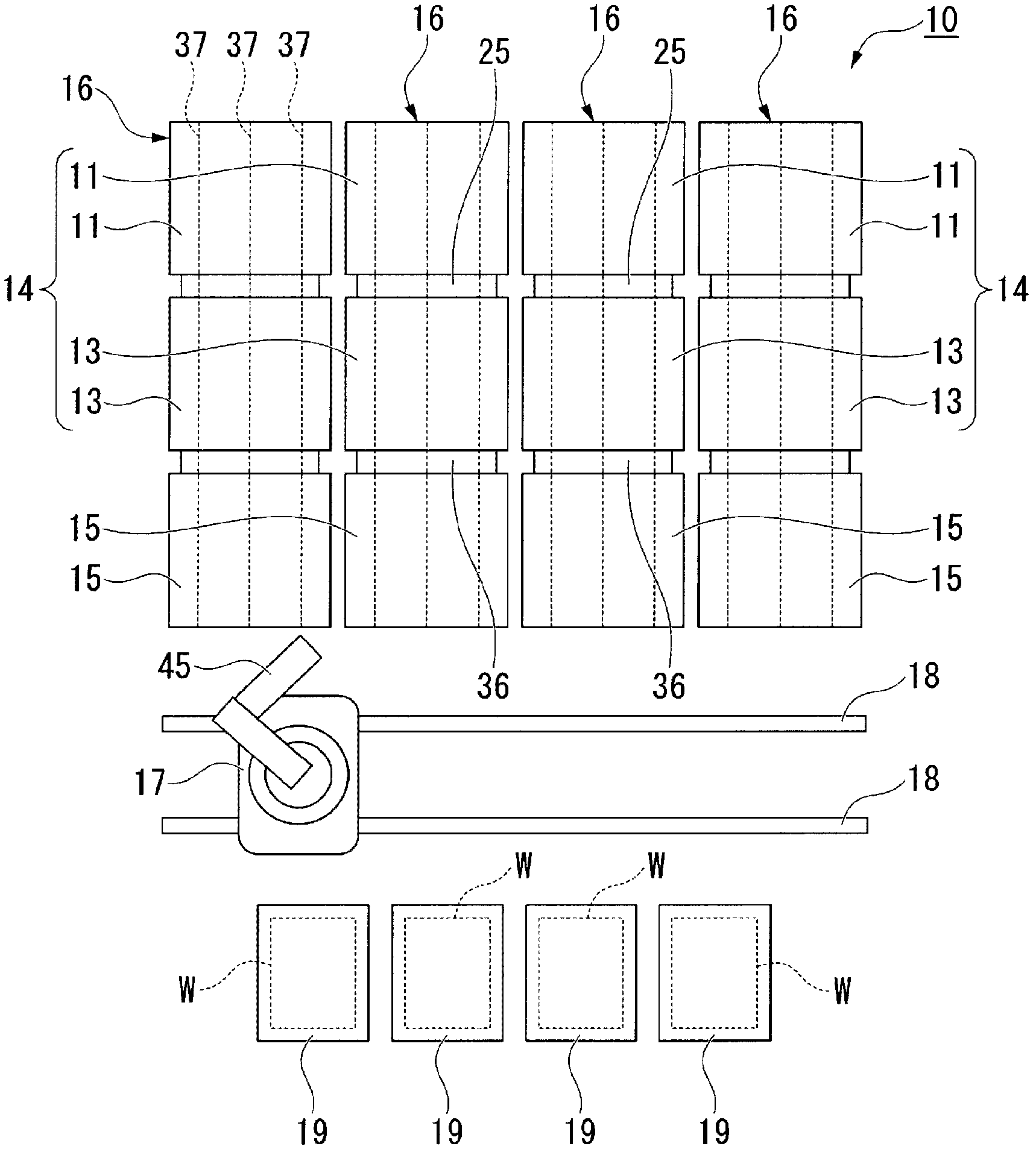
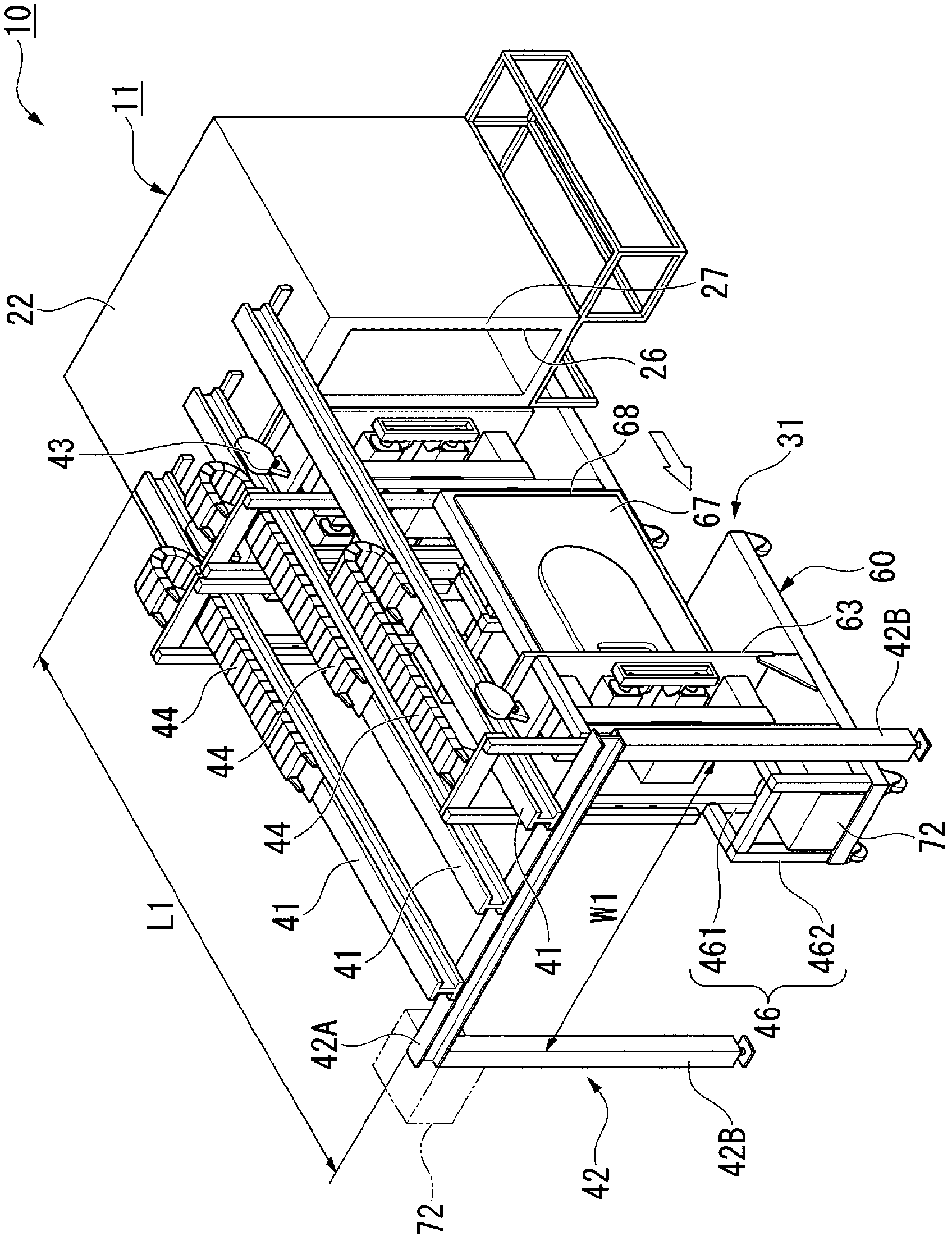
[0037] figure 1 It is a figure schematically showing the structure of a film formation apparatus.

[0038] like figure 1 As shown, the film forming apparatus 10 includes: a film forming chamber 11 , a loading and unloading chamber 13 , a substrate loading and unloading chamber 15 , a substrate loading and unloading robot 17 , and a substrate storage box 19 .

[0039] In the film formation chamber 11 , for example, a microcrystalline silicon film can be formed on a plurality of substrates W at the same time.

[0040] The loading / unloading chamber 13 c...


PUM


Abstract

Disclosed is a film-forming apparatus (10) which includes: a film-forming chamber (11), which has an upper part (22) in the gravitational direction, and has a substrate (W) disposed therein such that the substrate (W) surface, on which a film is to be formed, is parallel to the gravitational direction; an electrode unit (31), which has a flat-board-like cathode (75) having a voltage applied thereto, and an anode (67) disposed to face the cathode (75) by being spaced apart from the cathode, and which is removably provided in the film-forming chamber (11); and an attaching / detaching rail (41), which is provided on the upper part of the film-forming chamber (11), in the direction wherein the electrode unit (31) is drawn from the film-forming chamber (11), and which guides the electrode unit (31).

Description

technical field [0001] The present invention relates to a film-forming apparatus used, for example, in the manufacture of thin-film solar cells. [0002] This application claims priority based on Japanese Patent Application No. 2009-179413 for which it applied on July 31, 2009, and uses the content here. Background technique [0003] Among the materials used in current solar cells, monocrystalline Si-type and polycrystalline Si-type materials account for more than half, and people are concerned about the shortage of Si materials. [0004] Therefore, in recent years, there has been an increased demand for thin-film solar cells with low manufacturing costs, little risk of material shortage, and on which a thin-film Si layer is formed. [0005] Furthermore, in addition to existing forms of thin-film solar cells having only an a-Si (amorphous silicon) layer, recently, there has been a search for conversion by laminating an a-Si layer and a μc-Si (microcrystalline silicon) layer...

Claims


Application Information

Patent Timeline
Patent Type & Authority Applications(China)
IPC IPC(8): H01L21/205C23C16/44
CPCC23C16/4587
Inventor 清水康男森胜彦松本浩一冈山智彦森冈和播磨幸一冈嶋邦彦
Owner ULVAC INC
Why Eureka
Try Eureka