Vacuum cleaner electric wire bobbin disk assembly

A technology for vacuum cleaners and wire coils, which is applied to electrical components, cable arrangement between relatively moving parts, cable installation, etc. Isokinetic motion and other issues to achieve the effect of improving practicability

Inactive Publication Date: 2005-01-19
LG ELECTRONICS (TIANJIN) APPLIANCES CO LTD
View PDF0 Cites 0 Cited by
  • Summary
  • Abstract
  • Description
  • Claims
  • Application Information

AI Technical Summary

Problems solved by technology

That is, there is the shortcoming that the wires wound on the rotating disk 4 are not neat in the above-mentioned prior art
[0012] The shortcoming in the above-mentioned prior art is caused by above-mentioned reel 4 can not do constant speed motion substantially
That is, at first, the strong elastic restoring force provided by the spring 6 rotates quickly, but later, the elastic restoring force of the spring 6 becomes weak, and the rotating speed also becomes slow.

Method used


Image

  • Vacuum cleaner electric wire bobbin disk assembly
  • Vacuum cleaner electric wire bobbin disk assembly
  • Vacuum cleaner electric wire bobbin disk assembly

Examples


Embodiment Construction

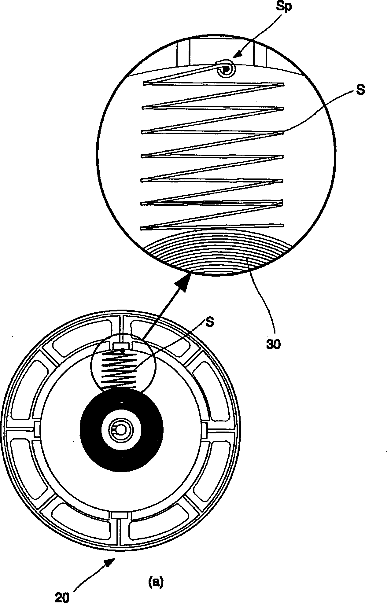
[0024] Figure 4 The structure of the reel 20 in the electric wire reel assembly of the present invention is shown. As shown, a spring 30 is provided inside the reel 20 . The reel 20 rotates around the support shaft H to unwind or wind the electric wires on the electric wire reel.

[0025] In addition, the spring 30 provided inside the above-mentioned reel 20 generates an elastic restoring force for winding the reel 20 . Its one side is connected on the rotatable reel 20, and the other side is connected on the fixed frame.

[0026] The spring 30 is provided inside the reel 20 , actually between the inner surface of the cylindrical winding member 24 around which the electric wire is wound and the inner diameter 26 of the support shaft H inserted.

[0027] In addition, according to the present invention, a coil spring S is provided on the outer side of the spring 30 . The outer portion of the spring is fixed by the fixing member Sp on the inner surface 22 of the winding memb...


PUM


Abstract

The invention relates to an electric wire winding plate assembly of the vacuum cleaner. It comprises a frame(10) fixed inside of the main body of the vacuum cleaner, a winding plate(12) capable of being installed on the said frame(10a) in a revolving way for winding the electric wire, and a spring(16) for exerting elastic force to winding plate along the winding direction. The spring is arranged between the internal surface of the winding assembly in the winding plate and inner diameter of the winder plate, and a set of elastic device with winding plate spring are set for elastic supporting the spring to inside between the internal surface and the spring.

Description

technical field [0001] The present invention relates to a vacuum cleaner wire reel assembly (Cordreel assembly forvacuumcleaner), and furthermore, relates to a vacuum cleaner wire reel that can ensure that the wires wound on the reel will not fall off and can be densely wound from the bottom components. Background technique [0002] figure 1 A perspective view showing the cord reel assembly of a typical vacuum cleaner, figure 2 A cutaway view showing a cord reel assembly of an existing vacuum cleaner. The electric wire reel assembly of the above-mentioned vacuum cleaner is installed on one side (for example, lower part) of the main body of the vacuum cleaner, and winds the electric wire for supplying power to the vacuum cleaner. [0003] As shown in the figure, the wire reel assembly includes: a frame 2 fixedly installed and a reel 4 rotatably installed around the supporting shaft 2a of the frame. The above-mentioned reel 4 has a circular shape, and the electric wire 8b...

Claims


Application Information

Patent Timeline
Patent Type & Authority Applications(China)
IPC IPC(8): A47L9/26
Inventor 柳明植
Owner LG ELECTRONICS (TIANJIN) APPLIANCES CO LTD
Why Eureka
Try Eureka