Surface light source device with frame having adhesive on reflector and circuit board and liquid crystal display device

a surface light source and reflector technology, applied in the direction of planar/plate-like light guides, lighting and heating apparatuses, instruments, etc., can solve the problems of insufficient brightness unsuitable for practical use, and inability to meet the requirements of use, so as to improve the light use efficiency reduce the thickness of the surface light source device

Active Publication Date: 2012-11-13
ORMON CORP
View PDF10 Cites 12 Cited by
  • Summary
  • Abstract
  • Description
  • Claims
  • Application Information

AI Technical Summary

Benefits of technology

[0013]One or more embodiments of the present invention provides a thin surface light source device that enables reliable locating of a light guide plate and a light source along the thickness thereof. One or more embodiments of the present invention provides a thin surface light source device with good light use efficiency.

Problems solved by technology

Also, since the light sources 19 are merely inserted within the openings 18 in the light guide plate 13, the light sources 19 are not fixed sufficiently firmly, resulting in unsatisfactorily accurate locating of the light sources 19 along the thickness of the light guide plate 13.
Even if a light source that is as thin as the light guide plate 13 exists, such a thin light source presumably gives off light of a small quantity, which leads to insufficient brightness of the surface light source device and may not be suitable for practical use.

Method used


Image

  • Surface light source device with frame having adhesive on reflector and circuit board and liquid crystal display device
  • Surface light source device with frame having adhesive on reflector and circuit board and liquid crystal display device
  • Surface light source device with frame having adhesive on reflector and circuit board and liquid crystal display device

Examples


Embodiment Construction

[0040]Hereinafter, preferred embodiments of the present invention are described with reference to the accompanying drawings. In embodiments of the invention, numerous specific details are set forth in order to provide a more thorough understanding of the invention. However, it will be apparent to one of ordinary skill in the art that the invention may be practiced without these specific details. In other instances, well-known features have not been described in detail to avoid obscuring the invention.

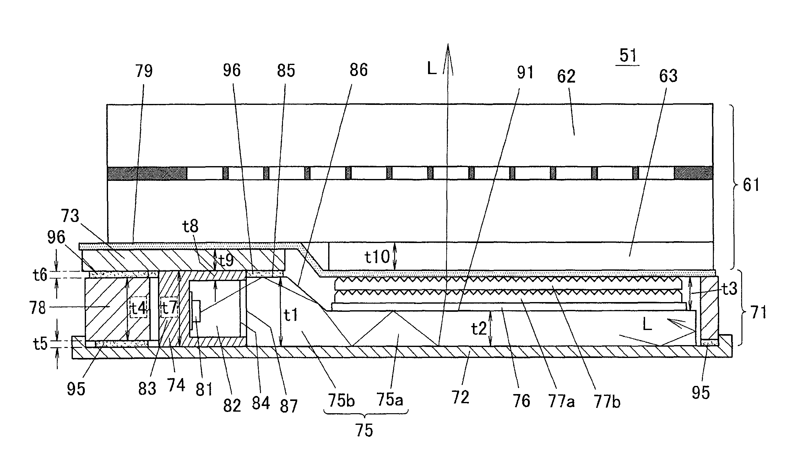
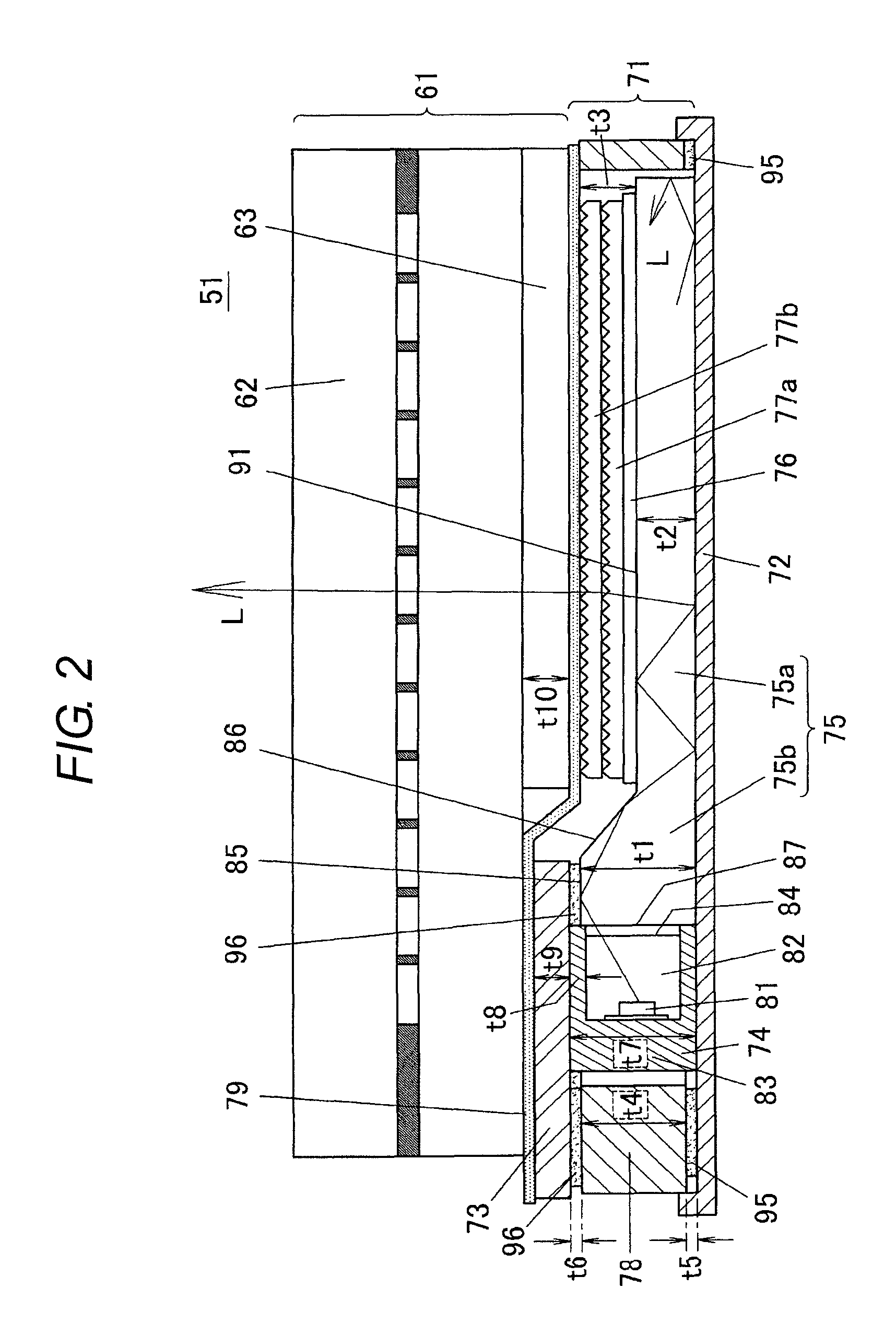
[0041]FIG. 2 is a cross-sectional view of a liquid crystal display device 51 according to one embodiment of the present invention. The liquid crystal display device 51 includes a liquid crystal panel unit 61 and a surface light source device 71 (backlight) of a sidelight type. FIG. 3 is an exploded perspective view of the surface light source device 71. FIGS. 4A to 7 are perspective views illustrating portions of the surface light source device 71. The structures of the surface light so...


PUM

PropertyMeasurementUnit
heightaaaaaaaaaa
heightaaaaaaaaaa
thicknessaaaaaaaaaa

Abstract

A surface light source device has a reflector plate, a light guide plate placed on an upper surface of the reflector plate, the light guide plate including a light guide plate main body having a light outgoing area, and a light introducing portion provided continuously from an end of the light guide plate main body, the light introducing portion having an upper surface side projected from an upper surface of the light guide plate main body in such a manner as to have a maximum thickness greater than a thickness of the light guide plate main body, a light source disposed such that light emitted therefrom is introduced into the light guide plate from a light incidence surface of the light introducing portion, a frame-like member having a uniform thickness, the frame-like member being adhesively applied to the upper surface of the reflector plate in such a manner as to enclose the light guide plate and the light source, a wiring substrate mounted at a lower surface thereof with the light source, the wiring substrate being adhesively applied to an upper surface of the frame-like member and to the upper surface of the maximum thickness area of the light introducing portion, and at least one optical sheet disposed on the upper surface of the light guide plate main body, the light introducing portion being sandwiched between the wiring substrate adhesively applied to the upper surface of the frame-like member and the reflector plate adhesively applied to the lower surface of the frame-like member.

Description

BACKGROUND OF THE INVENTION[0001]1. Technical Field[0002]The present invention relates to surface light source devices and liquid crystal display devices, and more specifically, to surface light source devices for use as backlights for liquid crystal display devices and to the liquid crystal display devices.[0003]2. Related Art[0004]With the reduction in weight and thickness of devices such as mobile phones, the liquid crystal display devices for use in such mobile phones are desired to have lighter weights and reduced thicknesses. The surface light source devices for use as backlights for the liquid crystal display devices are desired to have even more reduced thicknesses accordingly.[0005]An exemplary surface light source device with a reduced thickness is disclosed in JP2009-054327A (a planar light unit). A cross section of a liquid crystal display device using the surface light source device is illustrated in FIG. 1.[0006]In a surface light source device 11 described in JP2009-0...

Claims


Application Information

Patent Timeline
Patent Type & Authority Patents(United States)
IPC IPC(8): G02F1/1335F21V7/04
CPCG02B6/002G02B6/0081G02F1/133615G02B6/0083G02F1/1335
Inventor YABE, MAMORU
Owner ORMON CORP
Why Eureka
Try Eureka