

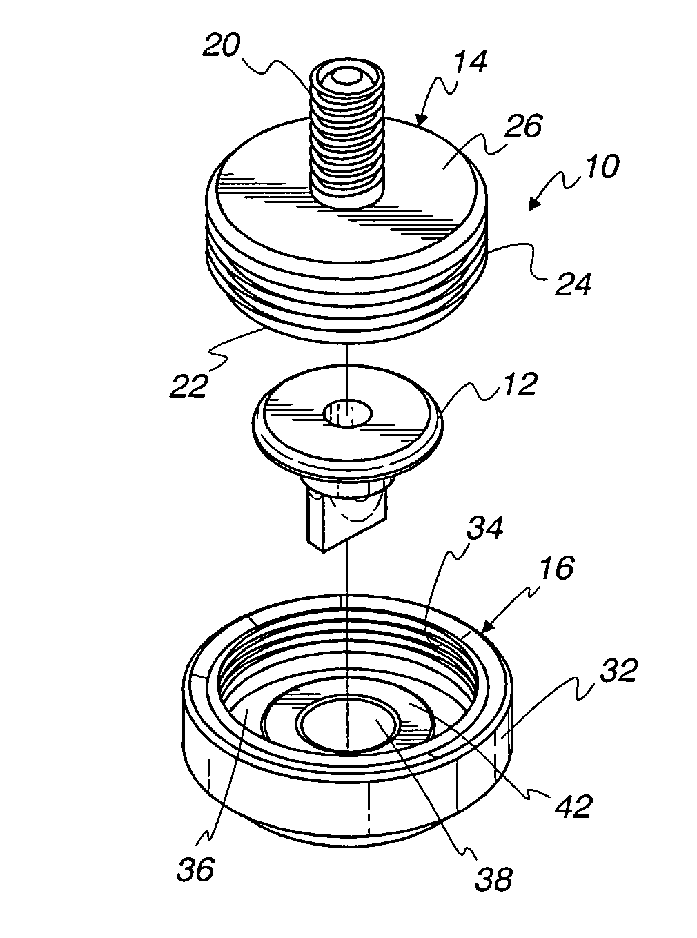
Vacuum breaker arrangement with externally protruding collapsible valve part
a vacuum breaker and collapsible technology, applied in mechanical equipment, functional valve types, transportation and packaging, etc., can solve the problems of increasing vacuum and impairing the operation of the engine, and achieve the effect of reducing pressure, accurately positioning the valve part, and being easy to adap
- Summary
- Abstract
- Description
- Claims
- Application Information
AI Technical Summary
Benefits of technology
Problems solved by technology
Method used
Image

Examples
Embodiment Construction
[0028]The invention disclosed herein is, of course, susceptible of embodiment in many different forms. Shown in the drawings and described hereinbelow in detail are preferred embodiments of the invention. It is understood, however, that the present disclosure is an exemplification of the principles of the invention and does not limit the invention to the illustrated embodiments.
[0029]For ease of description, fuel tank safety equipment utilizing a vacuum breaker arrangement embodying the present invention is described below in its usual assembled position as shown in the accompanying drawings, and terms such as upper, lower, horizontal, longitudinal, etc., may be used herein with reference to this usual position. However, the fuel tank safety equipment may be manufactured, transported, sold or used in orientations other than and described and shown herein.
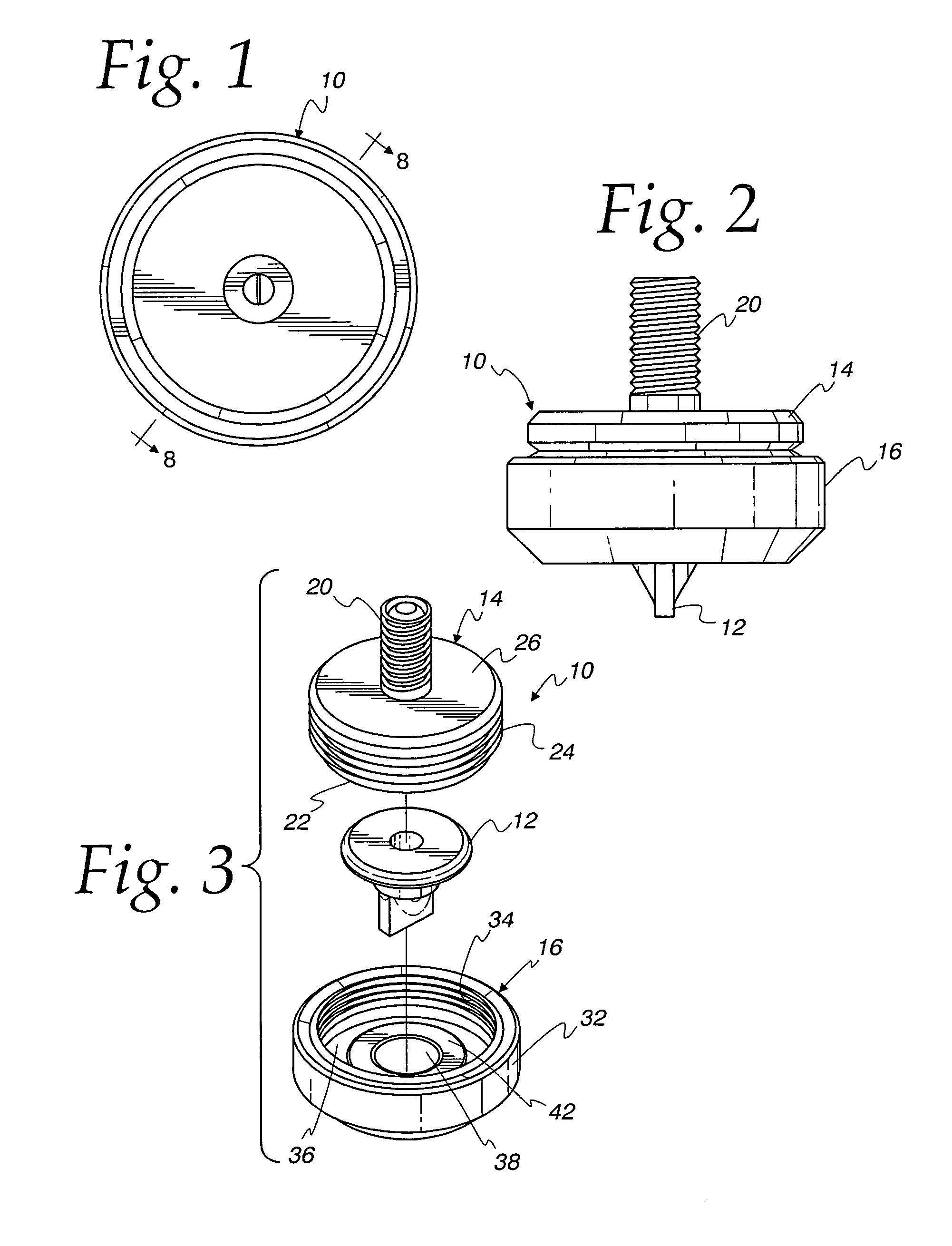
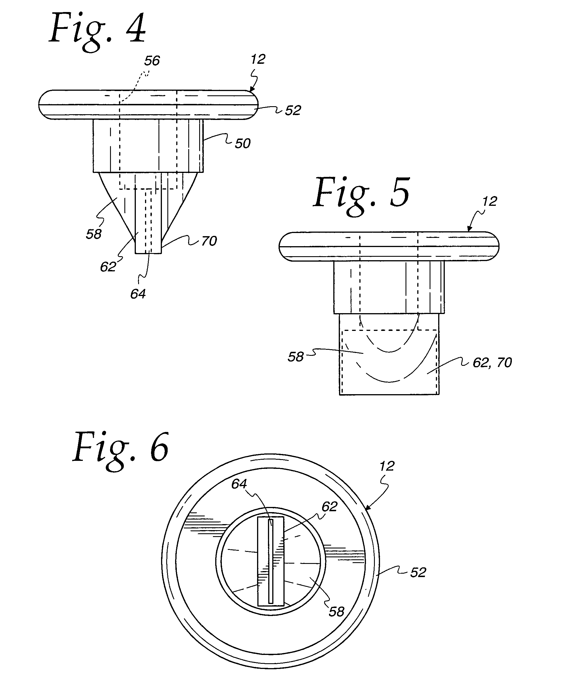
[0030]As will be seen herein, different types of apparatus embodying the present invention are described. Generally speaking, FIGS...
PUM
 Abstract
Description
Claims
Application Information