
Multi-view endoscopic imaging system

a multi-view, endoscopic technology, applied in the field of imaging devices, can solve the problems of mechanical complexity and complicated arrangement, and achieve the effect of reducing the light level and eliminating spurious weak images

Active Publication Date: 2012-11-27
TECHNION RES & DEV FOUND LTD
View PDF10 Cites 10 Cited by
  • Summary
  • Abstract
  • Description
  • Claims
  • Application Information

AI Technical Summary

Benefits of technology

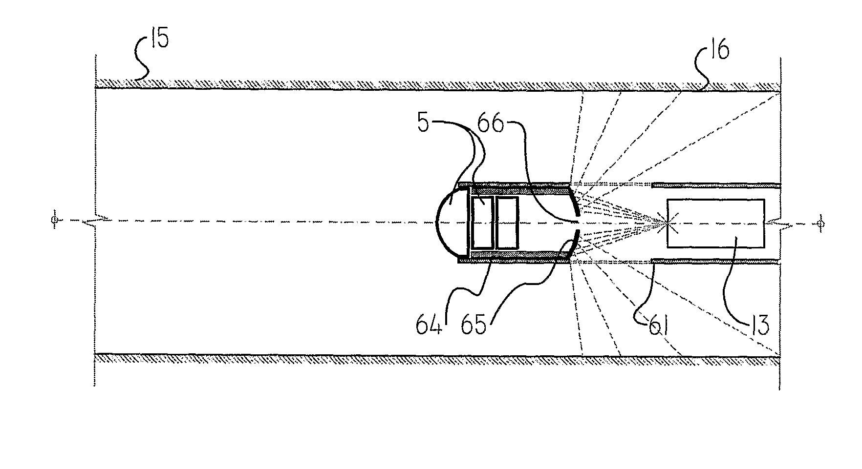
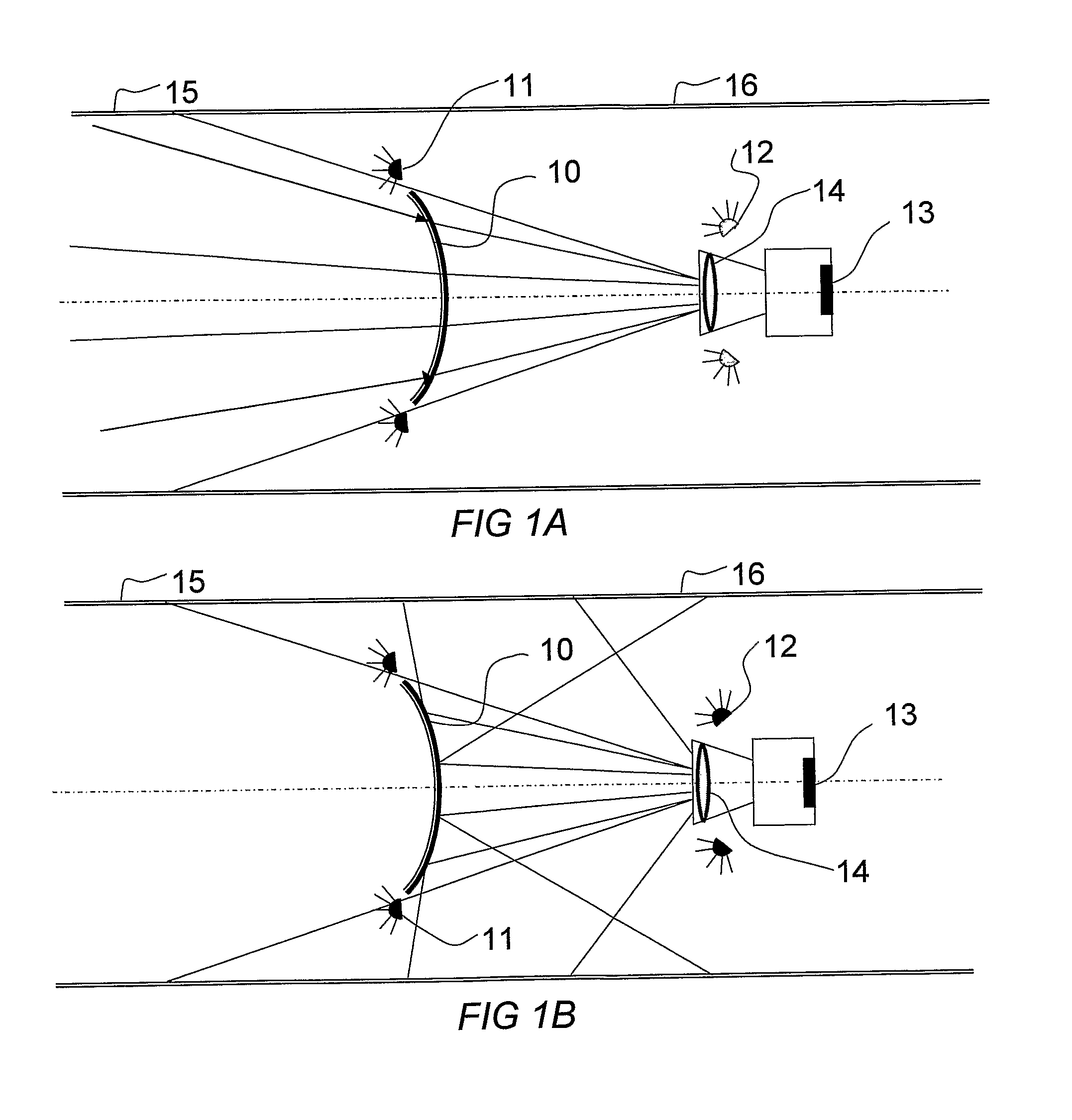
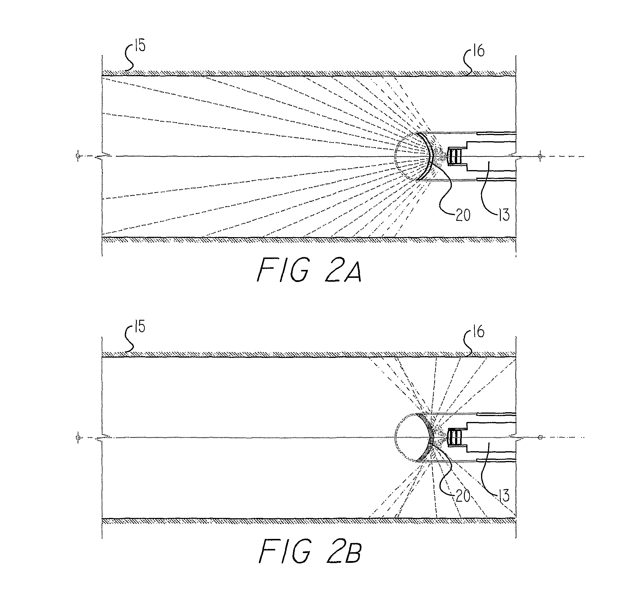
[0008]The present disclosure describes endoscopic illumination and imaging systems and methods for enabling observation of both the forward and rearward directions in a lumen or cavity, whether simultaneously or sequentially, using only a single imaging device. According to one implementation, the system utilizes the effects of a partially reflective mirror to respectively transmit and reflect light from the different portions of the internal lumen or cavity, and uses separate groups of illumination sources to illuminate one or the other section of the lumen or cavity, such that the illuminated section is preferentially imaged by virtue of its increased light level. Methods are described of eliminating the spurious weak images obtained when light from the illuminated section reaches the non-illuminated section and is imaged from there. Such methods use signal processing manipulation of the images obtained.
[0010]Similar imaging effects can be obtained using another exemplary system in which the mirror is switched between a reflective or transmissive function by the simple mechanical expediency of swinging it into or out of the line of sight of the camera. When in position, it reflects the rearward view into the camera lens; when swung out of position, the camera images only the forward view of the lumen. In such an instrument, the mirror can be full reflective for increased optical performance.
[0018]The system may further comprise an image processing unit which subtracts a processed first image of the inside surface of the lumen proximal to the mirror obtained when the first illuminating system is activated, from a second image of the inside surface of the lumen distal to the mirror obtained when the second illuminating system is activated, such that spurious effects in the second image arising from illumination of the lumen proximal to the mirror by light from the second illumination system, is reduced.
[0019]Alternatively, the system may further comprise an image processing unit which subtracts a processed first image of the inside surface of the lumen distal to the mirror obtained when the second illuminating system is activated, from a second image of the inside surface of the lumen proximal to the mirror obtained when the first illuminating system is activated, such that spurious effects in the second image arising from illumination of the lumen distal to the mirror by light from the first illumination system, is reduced.

Problems solved by technology

The camera can be fixed and the mirror moveable, or alternatively, the mirror can be fixed and the camera moveable, or both can be moveable, though that arrangement is mechanically more complex.

Method used


Image

  • Multi-view endoscopic imaging system
  • Multi-view endoscopic imaging system
  • Multi-view endoscopic imaging system

Examples


Embodiment Construction

[0051]Reference is now made to FIGS. 1A and 1B, which illustrate schematically an exemplary endoscopic multi-view camera system, which operates using illumination switching to illuminate separate sections of a lumen into which the endoscope is inserted. The device preferably comprises a forward looking camera 13 having an imaging lens 14 which should provide a wide field of view for most convenient ease of use, a field of view of at least 70° being advisable. The camera may be understood to include a pixilated digital sensor, such as a CCD or CMOS array, and an optical system delivering the image onto the sensor. Alternatively a fiber optic camera system may be used, in which a fiber optical system delivers the image to a remote camera. The camera may also incorporate image processing software modules, or these may be incorporated in a separate computing device located external to the endoscope, as is known in the art.

[0052]In front of the camera, a partially reflective mirror 10 ma...


PUM


Abstract

Endoscopic illumination and imaging systems for enabling observation of both the forward and rearward directions in a lumen using only a single imaging device. According to one implementation, the system utilizes the effects of a partially reflective mirror to respectively transmit and reflect light from the different portions of the lumen or cavity, and uses separate groups of illumination sources to illuminate one or the other section of the lumen, such that the illuminated section is preferentially imaged by virtue of its increased light level. In a second implementation, electrically switched mirrors are used, having properties switched between a transmissive and a partially reflective state, such that the mirror can be switched between imaging the regions forward of the camera when in a transmissive state, and imaging the regions rearward of the camera when in a reflective state. A mechanically swiveled mirror is described for the same purpose.

Description

CROSS-REFERENCE TO RELATED APPLICATIONS[0001]This application is a U.S. National Phase Application under 35 U.S.C. 371 of PCT International Application No. PCT / IL2008 / 001413, which has an international filing date of Oct. 26, 2008, and which claims priority benefit from U.S. Provisional Patent Application No. 60 / 996,008, filed Oct. 24, 2007, the contents of which are herein incorporated by reference in their entirety.FIELD OF THE INVENTION[0002]The present invention relates to the field of imaging devices for use in lumens, capable of viewing in multiple directions, especially for endoscopic use.BACKGROUND OF THE INVENTION[0003]Conventional endoscopes generally provide only a forward field of view. The field of view angle changes from endoscope to endoscope and can differ from narrow angle to a wide 170° field of view. The geometry of inspected medical and non-medical lumens is usually very complex and it would be useful to have the ability to image over a much wider field of view, ...

Claims


Application Information

Patent Timeline
Patent Type & Authority Patents(United States)
IPC IPC(8): A61B1/06
CPCA61B1/00096A61B1/00181A61B1/00183A61B1/0615A61B1/0623G02B23/2461A61B1/05H04N2005/2255A61B1/00177H04N23/555
Inventor GLOZMAN, DANIELHASSIDOV, NOAMSHOHAM, MOSHE
Owner TECHNION RES & DEV FOUND LTD
Learn More