Wing-fuselage section of an aircraft

a technology for fuselage and aircraft, which is applied in the direction of fuselage, aircraft stabilisation, aircraft accessories, etc., can solve the problems of large fittings, large construction and installation expenditure, and large manual work required for installation

Active Publication Date: 2012-12-04
AIRBUS OPERATIONS GMBH
View PDF16 Cites 17 Cited by
  • Summary
  • Abstract
  • Description
  • Claims
  • Application Information

AI Technical Summary

Benefits of technology

[0007]The invention provides a wing-fuselage section of an aircraft, which wing-fuselage section comprises a wing root at which the wing of the aircraft is connected to the fuselage, a fuselage region with fuselage frame elements that extent across the longitudinal direction of the aircraft, and a wing region with spars that extend in the direction of the wingspan. The invention provides for the spars of the wing region and for the fuselage frame elements of the fuselage region to form parts of an integral assembly that extends at least over a middle part of the wing and the fuselage region, including the wing roots.

Problems solved by technology

The various components or assemblies (wings, centre sections of the wings, fuselage), which in some cases may even be developed and produced in different plants before being joined during final assembly, result in very considerable construction and installation expenditure in order to safely master the above-mentioned problematical joining regions.
For example, massive fittings are required for the connections whose tolerances are to be met at great expenditure and whose installation requires a great deal of manual work.

Method used


Image

  • Wing-fuselage section of an aircraft
  • Wing-fuselage section of an aircraft
  • Wing-fuselage section of an aircraft

Examples


Embodiment Construction

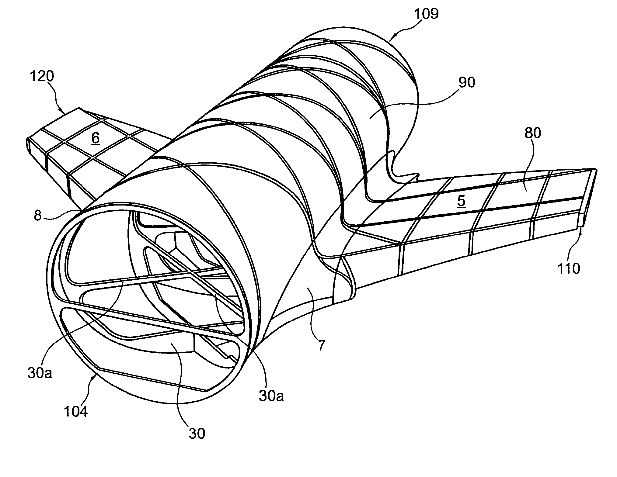
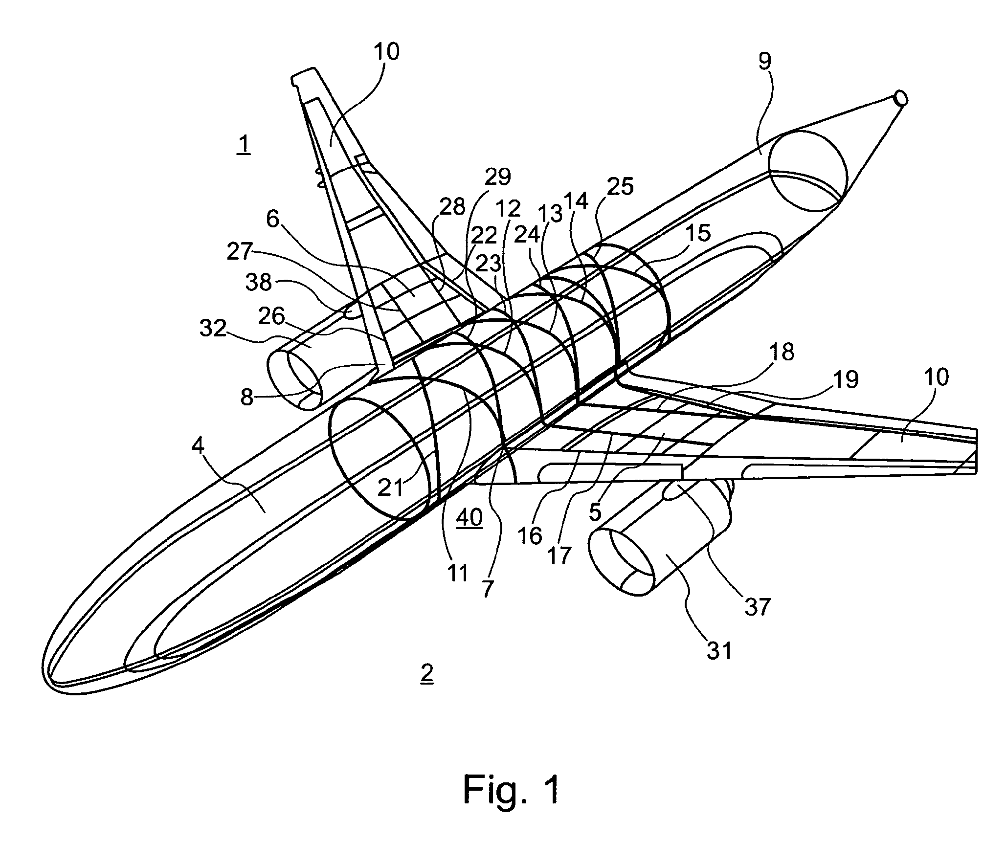
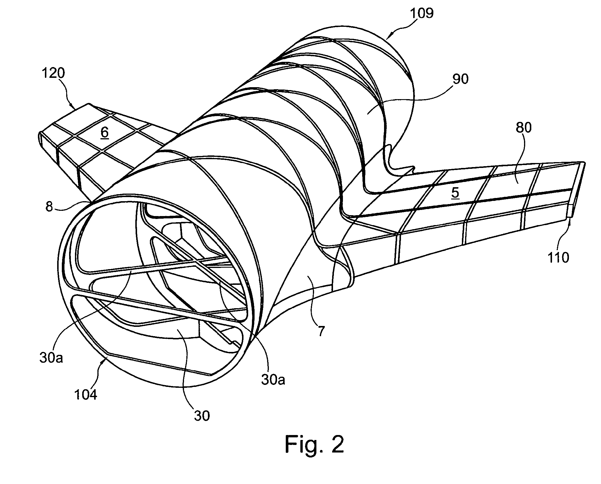
[0023]FIG. 1 shows a perspective view of essential components of a modern aircraft, in which a wing-fuselage section according to an exemplary embodiment of the invention is realised. The aircraft comprises a fuselage 2 and a wing 1 which by means of wing roots 7, 8 is connected to the fuselage 2. On the wing 1, engines 31, 32 are connected by means of carrier elements 37, 38 (pylons). A wing-fuselage section, overall designated by the reference character 40, comprises the wing root 7, 8 by which the wing 1 of the aircraft is connected to the fuselage 2 on both sides, as well as a fuselage region 3 with fuselage frame elements 11-15, 21-25 extending across the longitudinal direction of the aircraft, and on each side a wing region 5, 6 with spars 16-19 which extend in the direction of the wingspan, on one side, and spars 26-29 on the other side of the aircraft.

[0024]The wing-fuselage section 40 is realised in the form of an integral assembly comprising the spars 16-19 and 26-29 of th...


PUM


Abstract

A wing-fuselage section of an aircraft, which wing-fuselage section comprises a wing root at which the wing of the aircraft is connected to the fuselage, a fuselage region with fuselage frame elements that extent across the longitudinal direction of the aircraft, and a wing region with spars that extend in the direction of the wingspan. According to the invention, the spars of the wing region and the fuselage frame elements of the fuselage region form part of an integral assembly that extends at least over a middle part of the wing and the fuselage region, including the wing roots.

Description

CROSS-REFERENCE TO RELATED APPLICATIONS[0001]This application is a national phase entry under 35 U.S.C. §371 of International Application No. PCT / EP2008 / 054820, filed Apr. 21, 2008, published in English, which claims the benefit of the filing date of German Patent Application No. 10 2007 019 692.1-22 filed 26.04.2007, the disclosure of which application is hereby incorporated herein by reference.FIELD OF THE INVENTION[0002]The invention relates to a wing-fuselage section of an aircraft according to the precharacterising part of claim 1.TECHNICAL BACKGROUND[0003]Present-day wing-fuselage connections of aircraft comprise separate components that are joined during assembly. For example, there are wings that are attached on top of, or underneath, the fuselage by means of fittings without curtailing the space in the passenger cabin or in the cargo compartment. Structures are common in which the wing is installed in the form of a two-part, so-called centre-joint solution, or in the form o...

Claims


Application Information

Patent Timeline
Patent Type & Authority Patents(United States)
IPC IPC(8): B64C1/00
CPCB64C1/08B64C3/22
Inventor PAHL, GUNTER
Owner AIRBUS OPERATIONS GMBH
Why Eureka
Try Eureka