Aircraft using distributed electric ducted fan flap lift-rising system

A ducted fan, distributed technology, applied in the field of aircraft using distributed electric ducted fan flap lift system, can solve the problems of unsuitable use of electric mode, large lift coefficient, large frictional resistance, etc., to achieve improved Economy and load capacity, the effect of improving economy and load capacity, increasing the lift-to-drag ratio and lift

Inactive Publication Date: 2015-10-14
龙川
View PDF2 Cites 17 Cited by
  • Summary
  • Abstract
  • Description
  • Claims
  • Application Information

AI Technical Summary

Benefits of technology

This patented technology describes an improved design that enhances the performance of electrical propellers used by modern military drones or other types of vehicles (such as helicopters). By adding more wings per unit length compared to previous designs without increasing their overall size, they improve efficiency while reducing its own mass. Additionally, this new design reduces drag caused when flying over uneven surfaces like sandstorms, resulting in better control and safety measures. Overall, these improvements lead to increased payload capacities and economic benefits.

Problems solved by technology

Inventions described earlier were developed into a type called DFG (Disc Fan Lift) System used in helicopters or other types of vehicles such as drones. These improvements aim to improve performance without increasing their size while also reducing environmental impact caused by fuel usage.

Method used


Image

  • Aircraft using distributed electric ducted fan flap lift-rising system
  • Aircraft using distributed electric ducted fan flap lift-rising system
  • Aircraft using distributed electric ducted fan flap lift-rising system

Examples


Embodiment 1

[0019]The aircraft that can be formed by the combination of the fuselage and the fuselage and the distributed electric ducted fan flap lift system described in the first embodiment is different from the fuselage described in the second embodiment, the fuselage and the distributed electric duct The other parts of the aircraft that can be constituted by the combination of the fan flap increased lift system have the same structure, and the combination of the fuselage described in Embodiment 1 and the fuselage and the distributed electric ducted fan flap increase system can be achieved below. Taking the constituted aircraft as an example, continue to describe the structure of other parts of the aircraft.

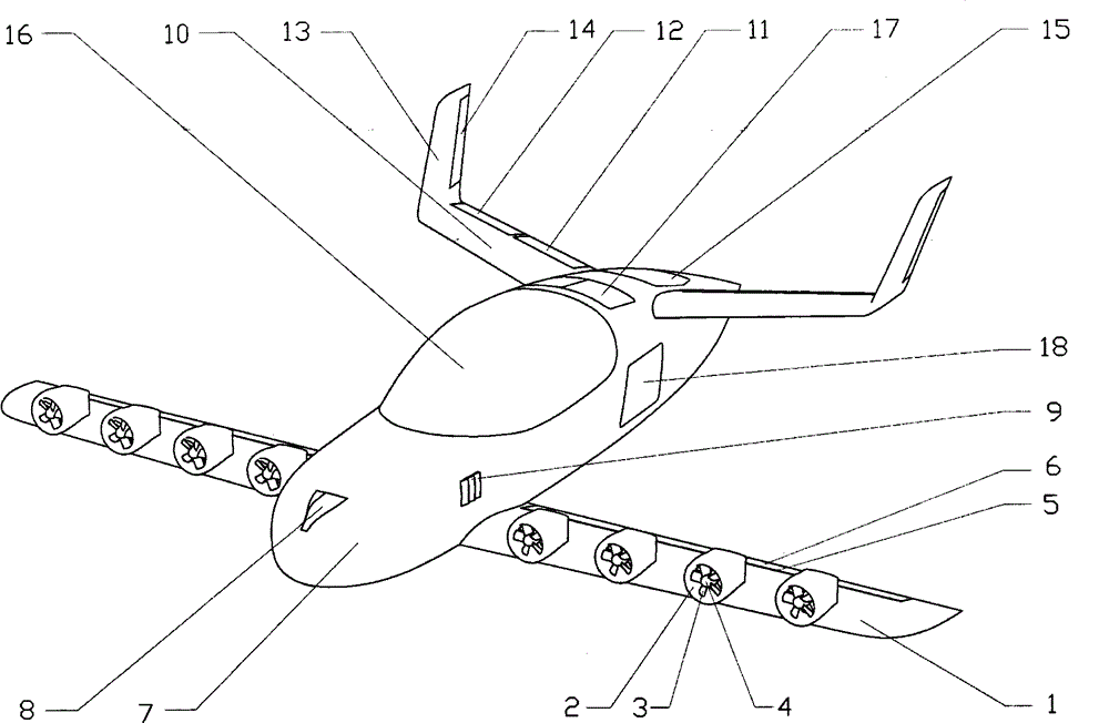
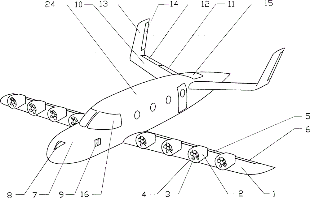
[0020] Such as figure 1 , shown in 2, the lift fan 20 is one, the air inlet of the lift fan 20 is provided with a cover plate 15 that can be opened and closed toward the head of the fuselage as required, and the exhaust port is provided with a longitudinal deflection panel that ...

Embodiment 2

[0036] The aircraft in the form of a business jet that can be formed by the combination of the fuselage and the fuselage and the distributed electric ducted fan flap increase system described in the second embodiment is the same as the fuselage and the distribution of the fuselage described in the first embodiment. The working process of the household form aircraft that can be formed by the combined mode of the electric ducted fan flap increasing the lift system is the same, so it is no longer repeated.

[0037] In this embodiment, when the aircraft is flying in the vertical take-off and landing state and the horizontal flight state, it is necessary to use the control stabilization system for manual stabilization.

[0038] Present embodiment aircraft is arranged on the front part of fuselage because two distributed electric ducted fan flaps increase lift system, and the duct 2 of each electric ducted fan has left and right two facades, and these facades are as The vertical tai...


PUM


Abstract

The present invention discloses an aircraft using a distributed electric ducted fan flap lift-rising system. The aircraft symmetrically arranges two distributed electric ducted fan flap lift-rising systems on both sides of the front middle part of the fuselage; the distributed electric ducted fan wing flap lift system has relatively large wingspan and aspect ratio; the number of electric ducted fans arranged on the leading edge is relatively large; the rear middle part of the fuselage is provided with a lift fan; rear wings are symmetrically disposed both sides of the rear middle part of the fuselage; the center of gravity of the aircraft is located in the middle of the fuselage; and the aircraft has a tandem wing layout. The aircraft of the present invention has the advantages of small friction, and no pollution and low noise of the electric ducted fan.

Description


Claims


Application Information

Patent Timeline
Owner 龙川
Why Eureka
Try Eureka