Method for controlling plasma flow of wing lift-rising apparatus

A plasma and high-lift device technology, applied in the direction of aircraft control, affecting the air flow flowing through the surface of the aircraft, aircraft parts, etc., can solve the problems of limited response speed and bandwidth, and achieve shortened run distance and short excitation response time , The effect of frequency bandwidth

Inactive Publication Date: 2014-01-22
AIR FORCE UNIV PLA
View PDF4 Cites 16 Cited by
  • Summary
  • Abstract
  • Description
  • Claims
  • Application Information

AI Technical Summary

Problems solved by technology

Active flow control methods currently researched mainly include boundary layer blowing / suction and synthetic jets, which can effectively suppress flow separation and improve lift coefficient. The need for wing lift device design

Method used


Image

  • Method for controlling plasma flow of wing lift-rising apparatus
  • Method for controlling plasma flow of wing lift-rising apparatus
  • Method for controlling plasma flow of wing lift-rising apparatus

Examples


Embodiment Construction

[0026] Now in conjunction with embodiment, accompanying drawing, the present invention will be further described:

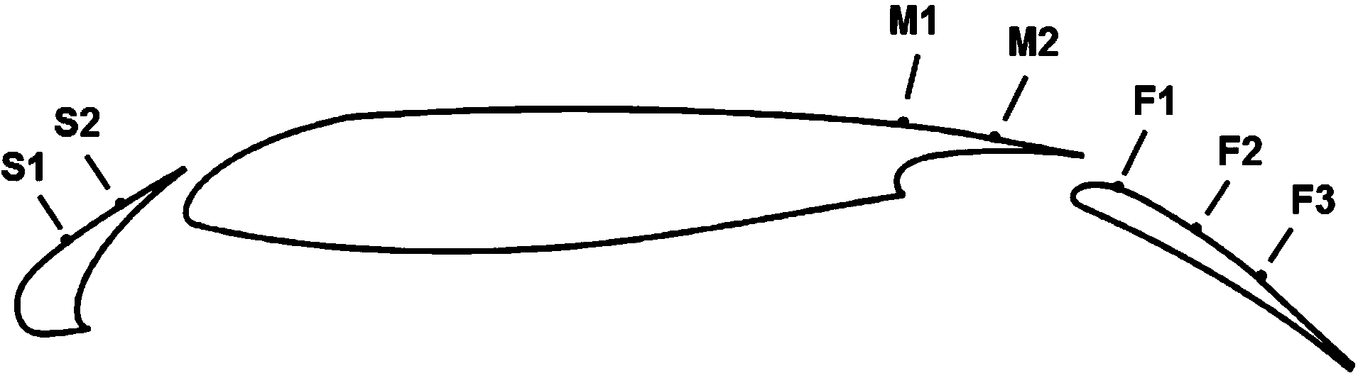
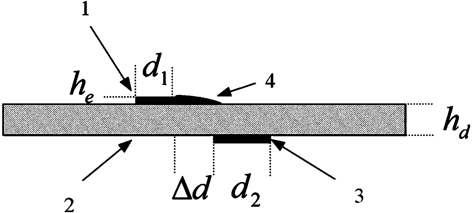
[0027] In the control method of this embodiment, the plasma exciter is laid on the suction surface of the leading edge slat, the suction surface of the trailing edge of the main wing and the suction surface of the trailing edge flap. The plasma exciter is composed of asymmetric layout electrodes separated by insulating material, the upper surface electrode of the insulating material is connected with the high-voltage end of the pulse plasma power supply, and the lower surface electrode is grounded. The laying position of the plasma actuator is at the leading edge and the trailing edge of the separation point. When the aircraft takes off and lands and opens the leading edge slats and trailing edge flaps, it sends an "on" signal to turn on the plasma actuator, and when the aircraft retracts the leading edge slats and trailing edge flaps, it sends out an "off" signa...


PUM


Abstract

The invention relates to a method for controlling plasma flow of wing lift-rising apparatus, and the technical scheme is characterized in that: plasma exciters are laid on the suction face of the leading edge slat, the suction face of the main wing trailing edge and the suction face of the trailing edge flap. The plasma exciter is composed of electrodes in asymmetric layout and separated by an insulating material, the electrode on the upper surface of the insulating material is connected with the high-voltage terminal of a pulse plasma power supply, and the electrode on lower surface is earthed. The laying positions of the plasma exciters are at the leading edge and the trailing edge of a separation point. When the leading edge slat and the trailing edge flat are deployed during the launching and the landing of an airplane, a signal of 'on' is emitted and the plasma exciters are turned on; and when the leading edge slat and the trailing edge flat are fold by the airplane, a signal of 'off' is emitted and the plasma exciters are turned off. The method helps to effectively control the flow separation of the suction faces of the leading edge slat, the main wing trailing edge and the trailing edge flap when the airplane is in a launching or landing state, substantially improving wing lift-drag ratio and maximum lift coefficient, and further improve the launching and landing weight of the airplane and shorten the running distance.

Description

technical field [0001] The invention belongs to the active flow control technology in the field of aircraft aerodynamic design, and relates to a method for controlling plasma flow of a wing, in particular to a method for controlling plasma flow of a wing high-lift device. Background technique [0002] Wing lift device design is a key technology for large transport aircraft and short take-off and landing aircraft to increase take-off weight, shorten take-off and landing run distance, and enhance airport adaptability, which determines the take-off, climb, go-around and landing performance of the aircraft . A major breakthrough in the design technology of the high-lift device will play a key role in the aerodynamic performance of the new generation of large aircraft, and it is also a very challenging research topic worldwide. Taking the Boeing 777 as an example, increasing the lift coefficient by 0.1 can reduce the pitch angle by 1°, shorten the height of the landing gear, and...

Claims


Application Information

Patent Timeline
Patent Type & Authority Applications(China)
IPC IPC(8): B64C21/00
Inventor 吴云李应红梁华赵光银韩孟虎
Owner AIR FORCE UNIV PLA
Why Eureka
Try Eureka