Vane airfoil profile of low power wind driven generator
A technology for wind turbines and blade airfoils, applied in the field of blade airfoils, can solve problems such as difficult design requirements for low-power generators, reduced efficiency of wind turbines, and decreased lift coefficient of blades, so as to improve performance and delay the separation point , the effect of increasing the curvature
Inactive Publication Date: 2010-08-25
NANJING UNIV OF AERONAUTICS & ASTRONAUTICS
View PDF5 Cites 16 Cited by
- Summary
- Abstract
- Description
- Claims
- Application Information
AI Technical Summary
Problems solved by technology
At this time, the lift coefficient of the blade will drop sharply, the drag coefficient will increase sharply, and the efficiency of the wind turbine will be greatly reduced. It is difficult to meet the design requirements of a low-power generator. normal work
Method used
View moreImage
Smart ImageViewing Examples
Examples
Embodiment Construction
Login to View More PUM
 Abstract
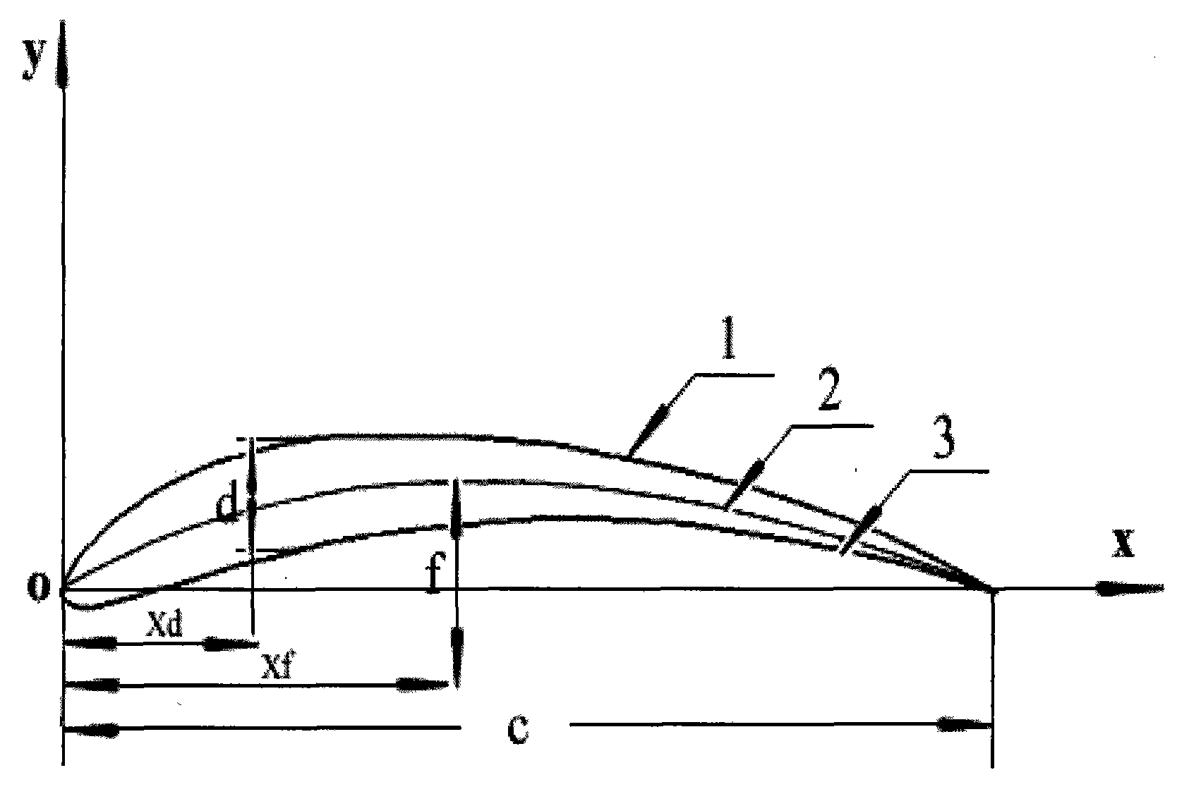
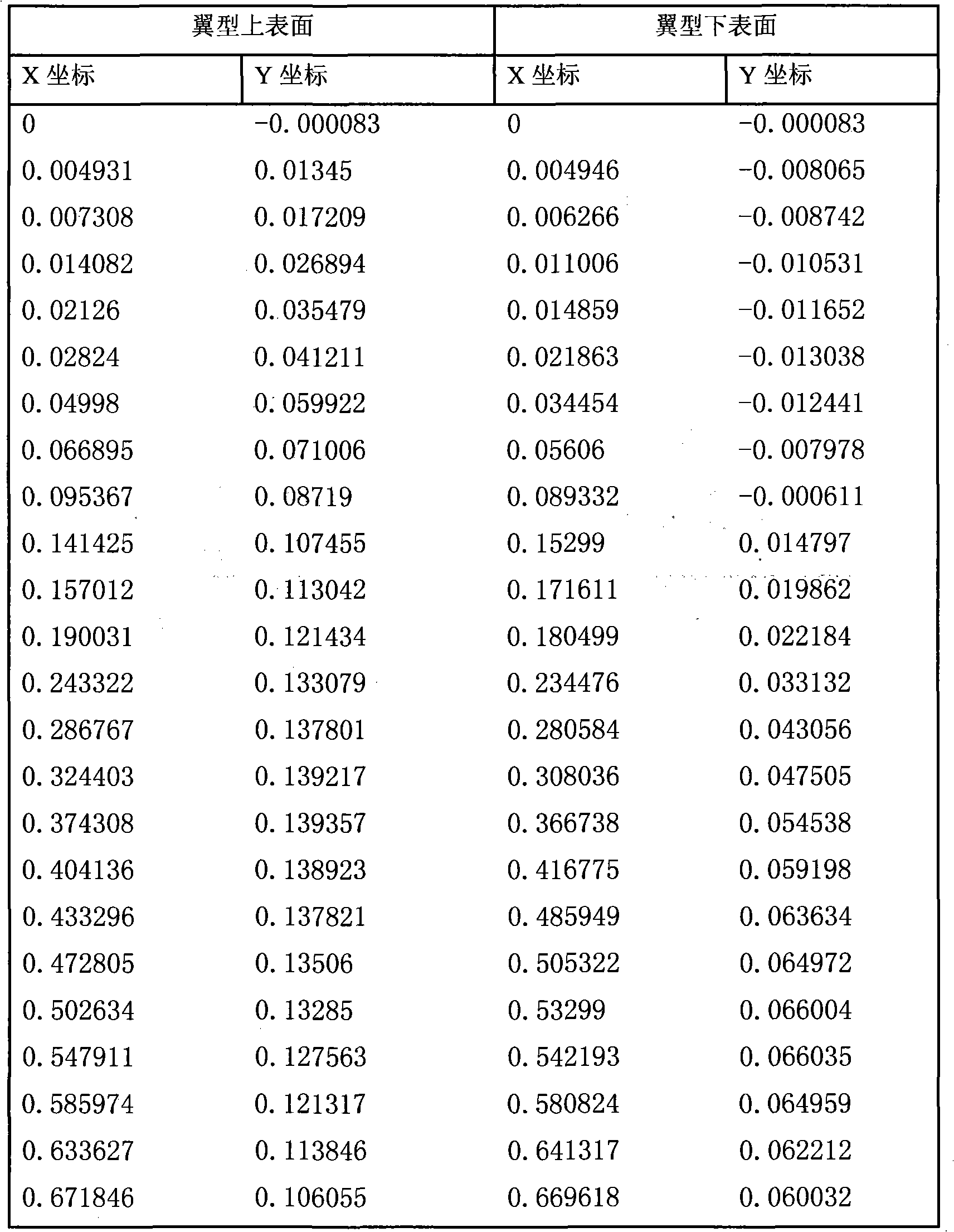
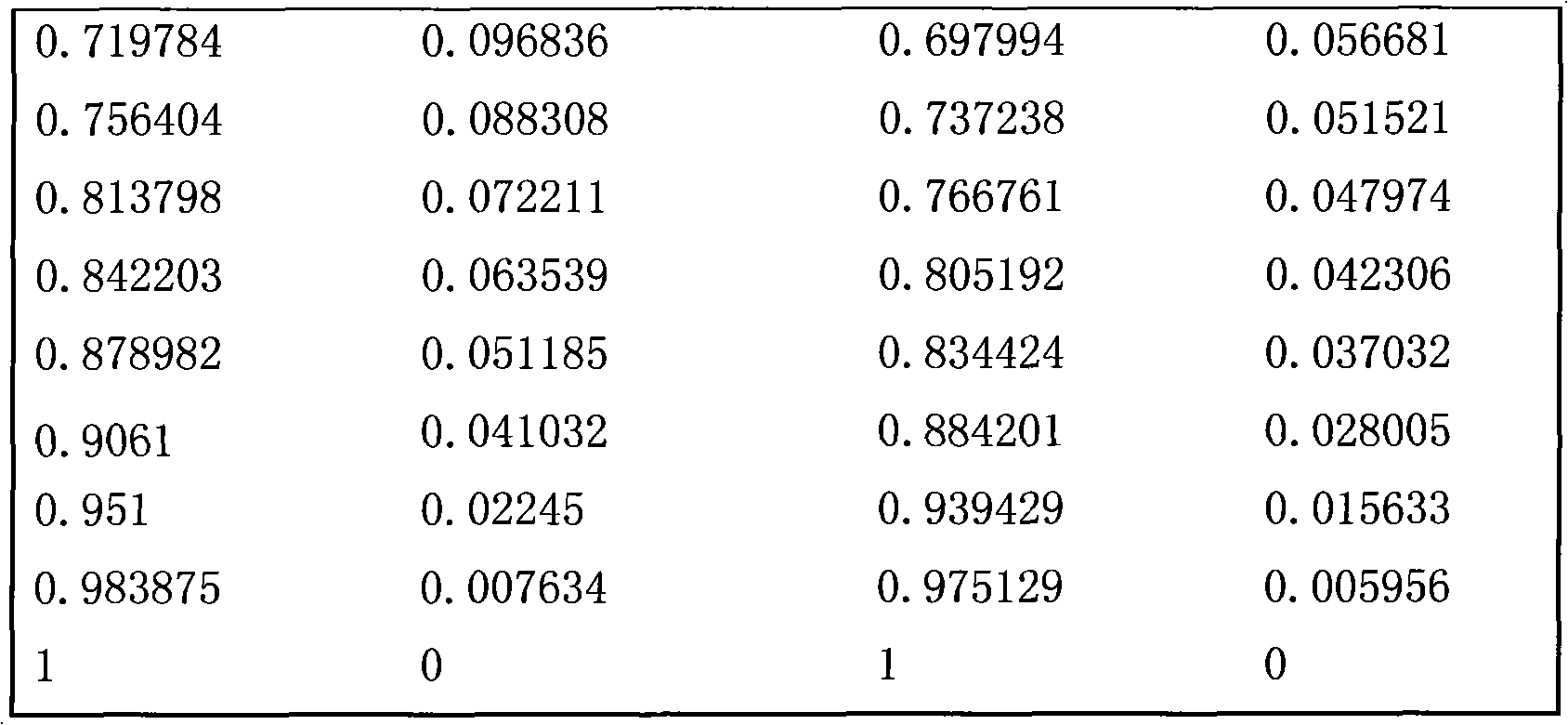
The invention discloses a vane airfoil profile of a low power wind driven generator, which is designed by adopting biological airfoil profile simulation technology and fluent software numerical simulation. The ratio of the maximum thickness d of the vane airfoil profile and the chord length c of the airfoil profile is d / c =9.83 percent. The maximum thickness position is x d / c =23.4 percent. The ratio of the maximum camber f of the airfoil profile and the chord length c of the airfoil profile is f / c=9.91 percent. The maximum camber position is the chord length part of x f / c=43.6 percent. Xd is the horizontal ordinate value of the maximum thickness part of the airfoil profile. Xf is the horizontal ordinate value of the maximum camber part of the airfoil profile. The coordinate axis origin is the front edge point of the airfoil profile. The horizontal ordinate x axis is superposed with chord length c and the direction points to the back edge of the airfoil profile from the front edge of the airfoil profile. Compared with the traditional conventional airfoil profile, the maximum thickness position xd and the maximum camber position xf of the invention are moved back and the invention has better lift efficiency and higher lift drag ratio. That is to say, the performance of the invention is improved on the whole.
Description
technical field The invention relates to an airfoil of a wind power generator, in particular to a blade airfoil of a low-power wind power generator, which is designed for the special requirements of relatively small generating power. Background technique With the gradual expansion of the promotion and application of small wind turbines, small wind turbines have gradually shifted from traditional agricultural, animal husbandry, and fishery applications to industrial production and residential life. However, the traditional low-power wind turbine airfoils are increasingly unsuitable for the current pursuit of high efficiency, energy saving and low noise. Small-power wind turbines have special characteristics such as short blades and low working Reynolds coefficients. Therefore, the influence of air viscosity on the blades of wind turbines has become a more important factor. Currently commonly used airfoils, such as: S809 airfoil, S822 airfoil, S823 airfoil, FFA-W1 airfoil, F...
Claims
Login to View More Application Information
Patent Timeline
 Patent Type & Authority Applications(China)
IPC IPC(8): F03D11/00F03D1/06
CPCY02E10/722Y02E10/72
Inventor 顾瑞徐惊雷张堃元
Owner NANJING UNIV OF AERONAUTICS & ASTRONAUTICS
Features
- R&D
- Intellectual Property
- Life Sciences
- Materials
- Tech Scout
- Unparalleled Data Quality
- Higher Quality Content
- 60% Fewer Hallucinations
Learn More Browse by: Latest US Patents, China's latest patents, Technical Efficacy Thesaurus, Application Domain, Technology Topic, Popular Technical Reports.
© 2025 PatSnap. All rights reserved.Legal|Privacy policy|Modern Slavery Act Transparency Statement|Sitemap|About US| Contact US: help@patsnap.com


