Automated operation of aircraft systems in inverted-v formations

a technology of inverted-v formation and automatic operation, which is applied in the direction of vehicle position/course/altitude control, process and machine control, instruments, etc., can solve the problems of inability to support the weight of the wings, structural and controllability concerns, and operational difficulties, etc., to achieve long endurance flight and high altitude

Inactive Publication Date: 2017-05-11
SYSENSE
View PDF1 Cites 17 Cited by
  • Summary
  • Abstract
  • Description
  • Claims
  • Application Information

AI Technical Summary

Benefits of technology

[0004]The teachings herein alleviate one or more of the above noted problems by using multi-aircraft systems in which the aircraft fly in precisely controlled formations to provide aerodynamic benefits to the individual aircraft and enable high altitude, long endurance flight.

Problems solved by technology

Such designs commonly result in operational difficulties and structural and controllability concerns.
These trade-offs are typical for any aircraft; however, for HALE UAS, the trade-offs are made stark by the severe restrictions faced by HALE aircraft on the limited amount of power that can be gathered through the solar panels and that is available for propulsion and powering on-board systems.
However, the weight limitation forces the use of less material to build these long wings, almost to the point that the wings cannot support their own weight.
However, in conditions in which a cross-wind or other disturbance occurs, the positions of the wake vortices of the leading aircraft may be affected.

Method used


Image

  • Automated operation of aircraft systems in inverted-v formations
  • Automated operation of aircraft systems in inverted-v formations
  • Automated operation of aircraft systems in inverted-v formations

Examples


Embodiment Construction

[0026]In the following detailed description, numerous specific details are set forth by way of examples in order to provide a thorough understanding of the relevant teachings. However, it should be apparent to those skilled in the art that the present teachings may be practiced without such details. In other instances, well known methods, procedures, components, and / or circuitry have been described at a relatively high-level, without detail, in order to avoid unnecessarily obscuring aspects of the present teachings.

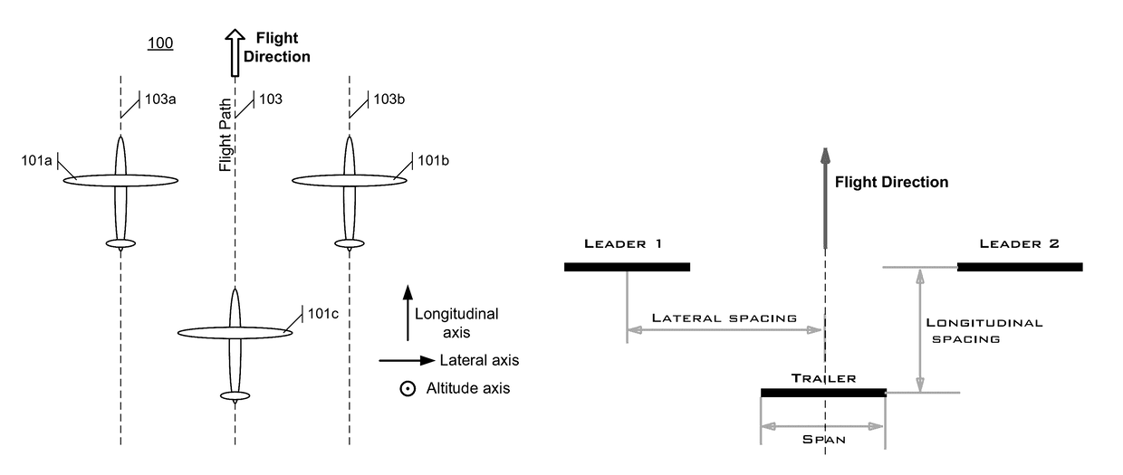
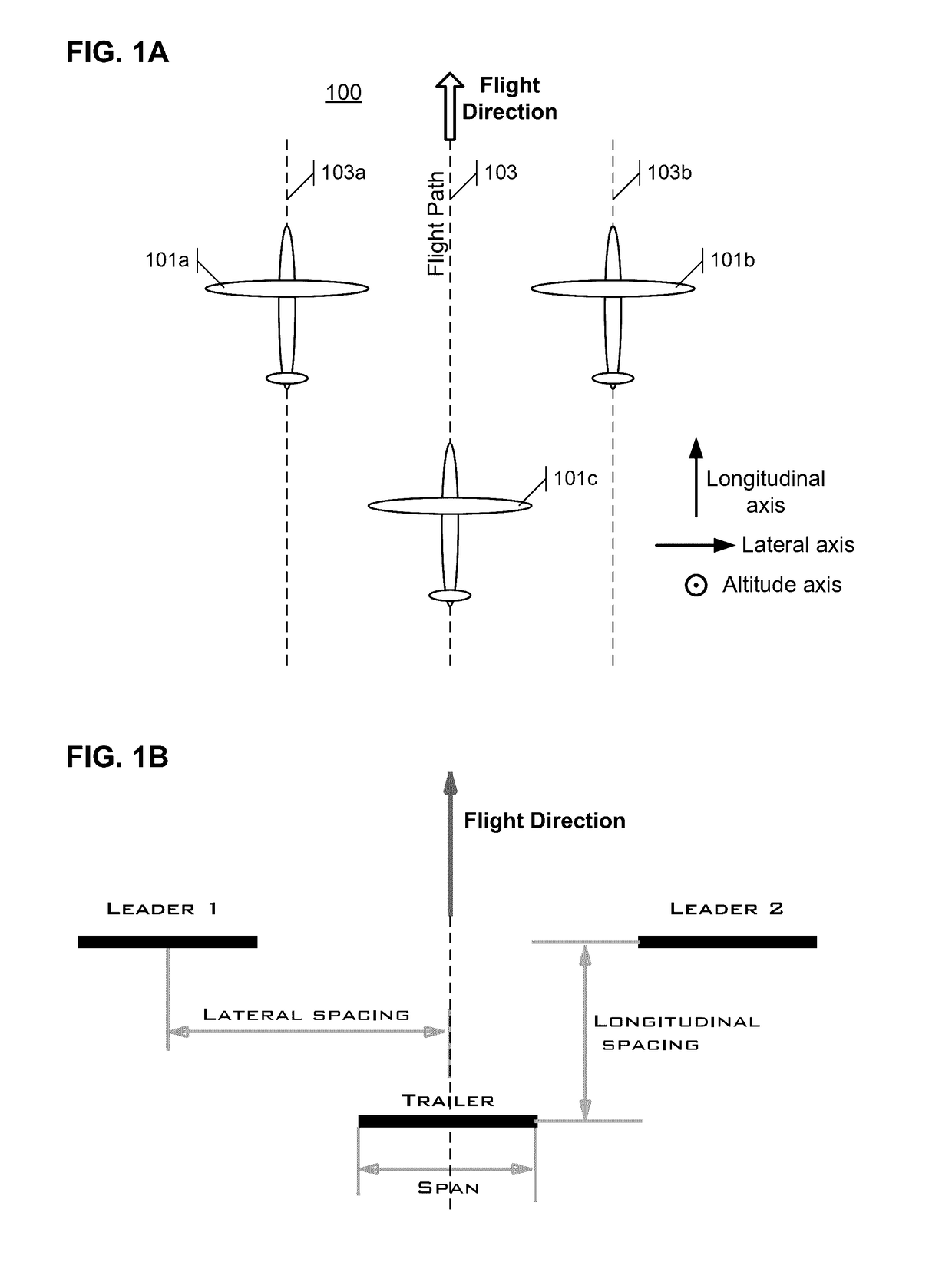
[0027]The above described limitations for a single HALE aircraft can be alleviated by flying several aircraft in a close and precisely controlled formation. Formation flight can provide aerodynamic benefits and other performance improvements to the individual aircraft in the formation such that HALE operation of the multi-aircraft system is possible. For example, the aircraft of the multi-aircraft system can be controlled in a flight formation in which wake vortices of tw...


PUM


Abstract

An aircraft system includes three or more aircraft and a flight control system. The flight control system controls flight of the aircraft so as to maintain the three aircraft in an inverted-V flight formation. Specifically, two leading aircraft fly along parallel flight paths and maintain substantially identical longitudinal positions along the parallel flight paths. A trailing aircraft flies along a flight path centered between the trailing vortices or flight paths of the leading aircraft and has a longitudinal position that is behind the two leading aircraft. The leading aircraft maintain a lateral separation distance such that the induced drag for the three aircraft formation is minimized for example by setting a lateral separation distance between wingtips of 0.8 to 1.0 wingspan of the trailing aircraft. The longitudinal separation between the leading and trailing aircraft is controlled by the flight control system based on operational objectives of the aircraft system.

Description

BACKGROUND[0001]High altitude, long endurance (HALE) unmanned aerial systems (UAS) are aerial systems which are designed to be capable of flight at altitudes above commercial air traffic (e.g., above 30,000 feet) with extended range (e.g., infinite range). Such systems are commonly also called atmospheric satellites (or “atmosats”). The systems have a wide range of applications, including (but not limited to) surveillance, telecommunication, and earth observation. The systems can be used in certain applications as alternatives to conventional satellites at a fraction of the cost.[0002]The conventional design for such systems is a single, solar-powered aircraft. Solar panels are typically mounted on the wings and other parts of the aircraft to harness energy from the sun to power the aircraft's electric motors. With this design paradigm, achieving long endurance flight requires very lightweight, high-aspect-ratio (long and slender) winged aircraft. Such designs commonly result in ope...

Claims


Application Information

Patent Timeline
Patent Type & Authority Applications(United States)
IPC IPC(8): G05D1/10B64C39/02
CPCG05D1/104B64C2201/143B64C39/024B64U2201/102
Inventor SPEYER, JASON L.ELDREDGE, JEFF
Owner SYSENSE
Why Eureka
Try Eureka