Chain link of a transport chain, transport chain of a conveyor and conveyor

a technology of transport chain and chain link, which is applied in the direction of conveyors, transportation and packaging, etc., can solve the problems of problematic use of such drive chains

Active Publication Date: 2015-12-08
DEMATIC LOGISTICS GMBH
View PDF17 Cites 7 Cited by
  • Summary
  • Abstract
  • Description
  • Claims
  • Application Information

AI Technical Summary

Benefits of technology

[0008]As a result of the elastic attachment of the thrust member to the base body of the chain link, the thrust member can be easily pushed upwards against the base body at the moment when holding adapters accumulate at a predefined spot of a conveyor, so that the chain link of the conveyor slides over the holding adapter to thereby allow to continue transport of further articles arranged on holding adapters on the chain link of the transport chain in a simple manner.
[0010]According to another advantageous feature of the present invention, a spring element may be provided to connect the thrust member with the base body. Advantageously the spring element is configured in the form of a spring leaf configured to extend at a slant for interconnecting the base body with the thrust member. Configuring the spring element as a spring leaf or elastic strip allows easy and cost-effective manufacture.
[0011]According to another advantageous feature of the present invention, the spring element can extend in relation to the base body and the thrust member at an angle between 5° and 30°. The presence of a substantially flat connection significantly facilitates elevation of the thrust members, when the holding adapters back up at a predefined position. As a result, the thus-forming back pressure applied by following adapters becomes very small so that wrinkling of, e.g., pieces of clothing guided by the adapters is avoided.
[0014]According to another advantageous feature of the present invention, the thrust member can have overlap portions on spaced-apart ends in the conveying direction for connection with a thrust member of an adjacent chain link. As a result, when a leading thrust member, as viewed in the conveying direction, is elevated by a backed-up holding adapter, the following thrust member is also slightly elevated so that the friction of the following thrust member on the backed up is reduced.
[0016]According to another advantageous feature of the present invention, running rollers can be supported by the head piece of the holding adapter and configured to roll in the rail profile, with the head piece having a coupler configured to extend beyond the running rollers and received in the at least one recess by a formfit when engaged with the thrust member, with the formfit between the thrust member and the coupler of the holding adapter being configured to resiliently deflect the thrust member in a direction of the base body of the chain link when the coupler of the holding adapter exerts a predefined force impact upon the thrust member, wherein the formfit to the holding adapter is releasable. The provision of such a headpiece of the holding adapter enables a low-friction disengagement of the holding adapter from the thrust member of the chain link.

Problems solved by technology

The use of such drive chains is problematic in regions where adapters pile up.

Method used


Image

  • Chain link of a transport chain, transport chain of a conveyor and conveyor
  • Chain link of a transport chain, transport chain of a conveyor and conveyor
  • Chain link of a transport chain, transport chain of a conveyor and conveyor

Examples


Embodiment Construction

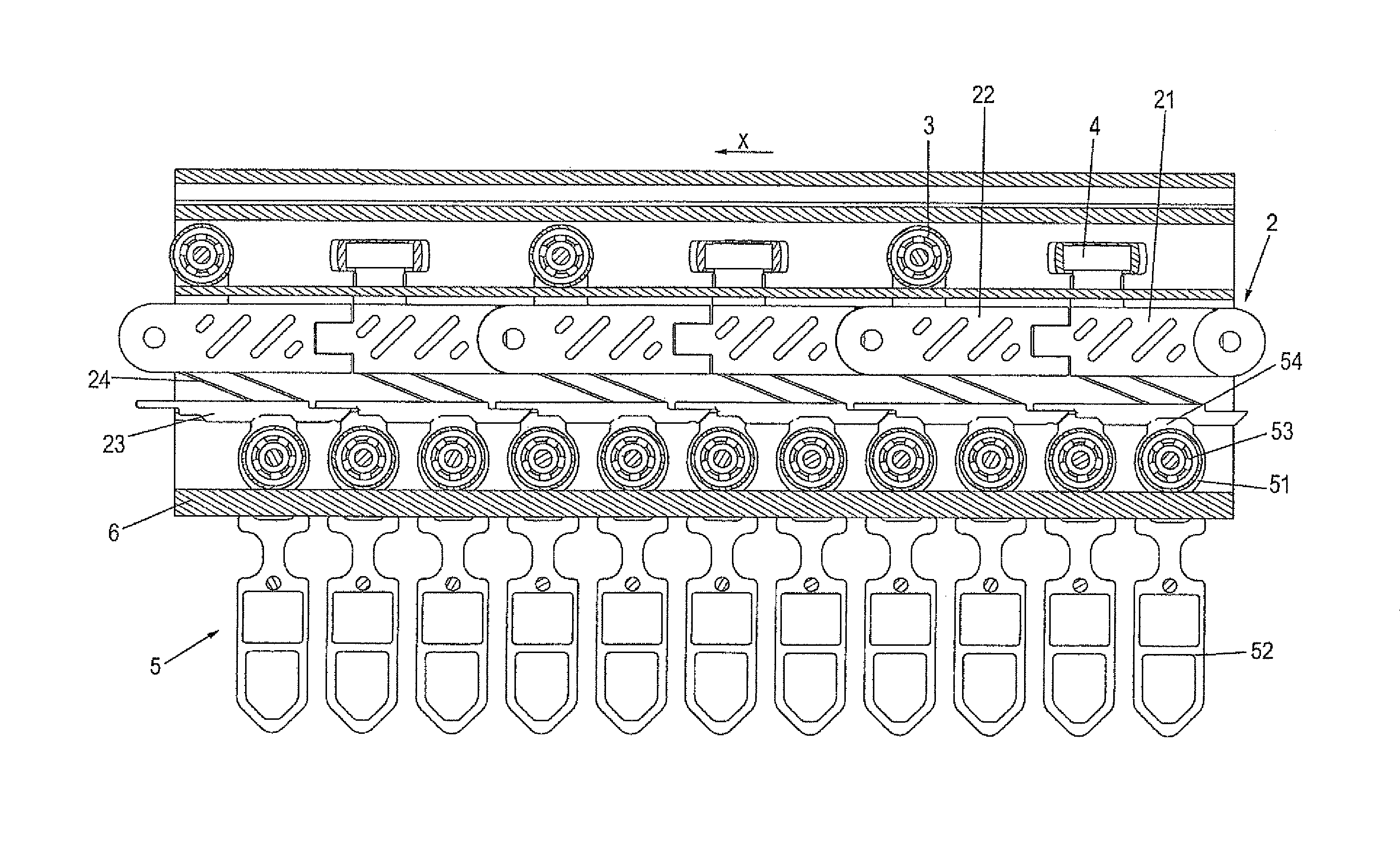
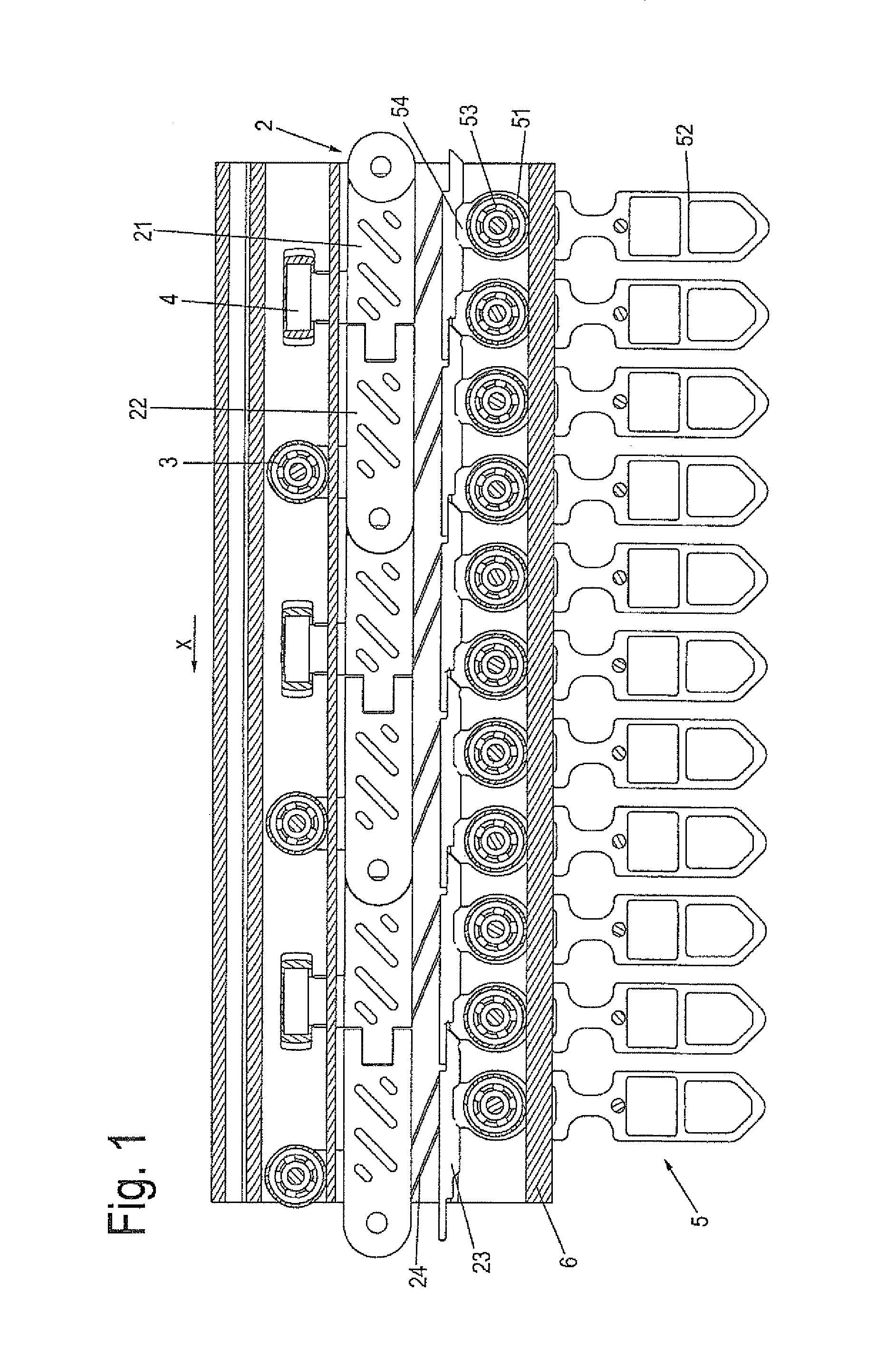
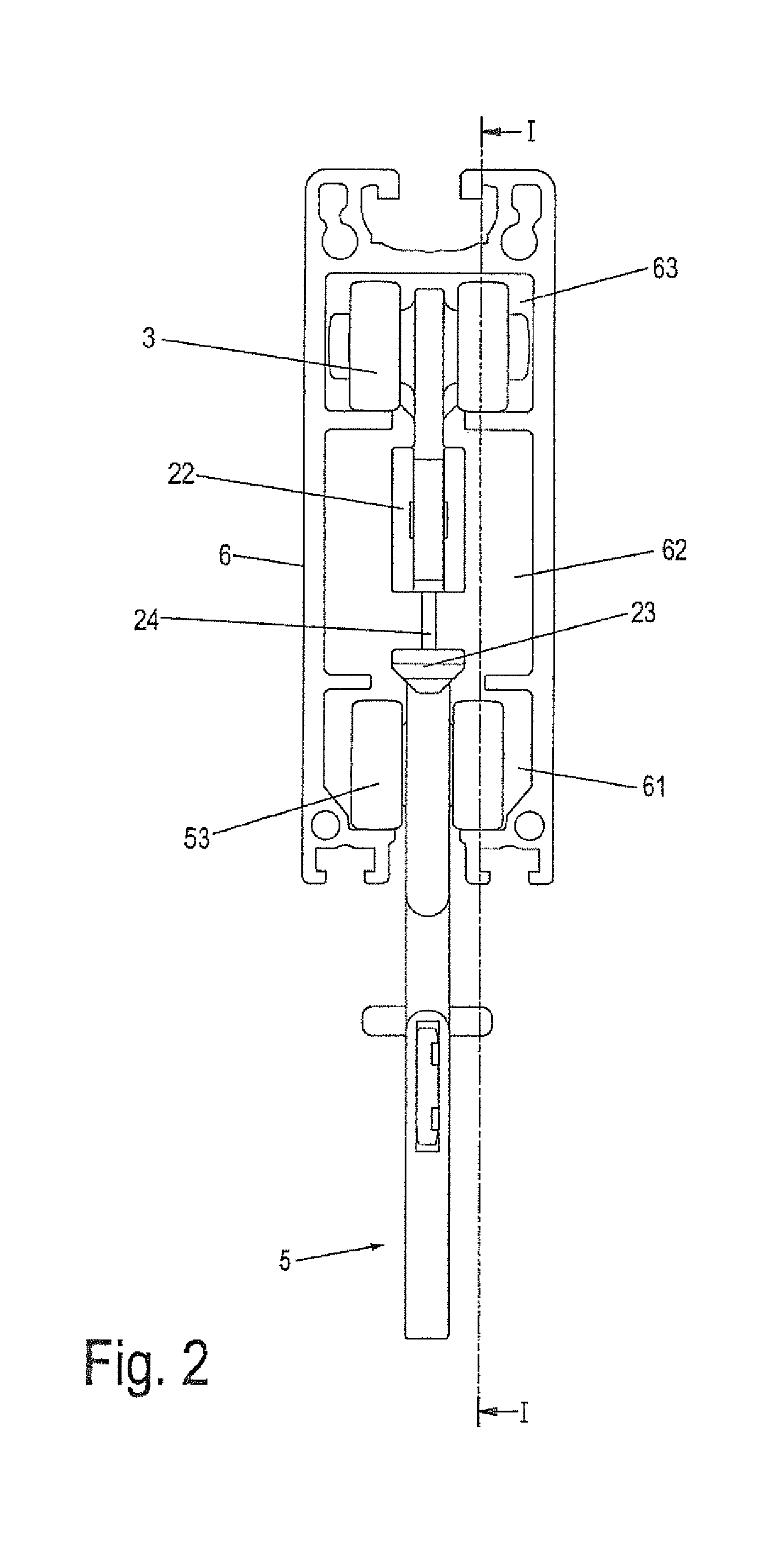
[0028]Throughout all the figures, same or corresponding elements may generally be indicated by same reference numerals. These depicted embodiments are to be understood as illustrative of the invention and not as limiting in any way. It should also be understood that the figures are not necessarily to scale and that the embodiments are sometimes illustrated by graphic symbols, phantom lines, diagrammatic representations and fragmentary views. In certain instances, details which are not necessary for an understanding of the present invention or which render other details difficult to perceive may have been omitted.

[0029]For purposes of description herein, the terms “upper,”“lower,”“right,”“left,”“rear,”“front,”“vertical,”“horizontal,” and derivatives thereof shall relate to the invention as oriented in the illustration and position of chain link, chain, holding adapter and the like, as selected by way of example in the respective figures. However, it is to be understood that the inven...


PUM


Abstract

A chain link of a transport chain of a conveyor for conveying an article hanging from a holding adapter includes a base body having lateral contact surfaces configured to enable friction rollers to be pressed there against for driving the transport chain. Arranged on the base body at ends in spaced-apart relationship in a conveying direction are coupling sections for swingable connection with a neighboring chain link. Bearings are formed on an upper side of the base body for support of running or guide rollers. A thrust member is connected vertically elastically to an underside of the base body and has an underside provided with at least one recess for formfittingly receiving a coupler of a head piece of the holding adapter for holding the article to be conveyed.

Description

CROSS-REFERENCES TO RELATED APPLICATIONS[0001]This application claims the priority of German Patent Application, Serial No. 10 2013 100 132.7, filed Jan. 8, 2013, pursuant to 35 U.S.C. 119(a)-(d), the disclosure of which is incorporated herein by reference in its entirety as if fully set forth herein.BACKGROUND OF THE INVENTION[0002]The present invention relates in general to the field of transport of articles.[0003]The following discussion of related art is provided to assist the reader in understanding the advantages of the invention, and is not to be construed as an admission that this related art is prior art to this invention.[0004]US 2012 / 0193192 describes a drive chain of an overhead conveyor for transporting hanging articles. The drive chain has a plurality of traction rod elements connected by coupling elements. Each traction rod element has a base body extending substantially along a conveying direction and having a first longitudinal end and an opposite second longitudina...

Claims


Application Information

Patent Timeline
Patent Type & Authority Patents(United States)
IPC IPC(8): B65G17/20B65G17/38
CPCB65G17/38B65G17/20B65G19/025
Inventor OTTO, THOMAS
Owner DEMATIC LOGISTICS GMBH
Why Eureka
Try Eureka