
Wireless transmission apparatus, wireless reception apparatus, and transmission method

a wireless reception and transmission method technology, applied in the field of wireless reception apparatus, wireless transmission apparatus, and transmission method, can solve the problems of inefficiency of resource use method and difficulty in changing the reception band of rel-8 lte terminal, and achieve the effect of efficient receiving information

Inactive Publication Date: 2012-12-04
FUJITSU TOSHIBA MOBILE COMM LTD
View PDF5 Cites 2 Cited by
  • Summary
  • Abstract
  • Description
  • Claims
  • Application Information

AI Technical Summary

Benefits of technology

[0012]The present invention has been made to meet the above requirement, and has as its object to provide a wireless transmission apparatus, a wireless reception apparatus, and a transmission method, which allow a narrowband reception apparatus to receive information without changing its specifications and a broadband reception apparatus to efficiently receive information when transmitting channel assignment information to the narrowband reception apparatus and the broadband reception apparatus using a common resource.
[0015]According to the present invention, it is therefore possible to provide a wireless transmission apparatus, a wireless reception apparatus, and a transmission method, which allow the narrowband reception apparatus of the first scheme to receive the information without changing its specifications and the broadband reception apparatus of the second scheme to efficiently receive the information.

Problems solved by technology

It is therefore difficult to change the reception band of the Rel-8 LTE terminal later at the start of the operation of the new system.
However, this resource use method cannot be efficient because the terminal existence ratio dynamically changes, as described above.

Method used


Image

  • Wireless transmission apparatus, wireless reception apparatus, and transmission method
  • Wireless transmission apparatus, wireless reception apparatus, and transmission method
  • Wireless transmission apparatus, wireless reception apparatus, and transmission method

Examples


Embodiment Construction

[0026]An embodiment of the present invention will now be described with reference to the accompanying drawing.

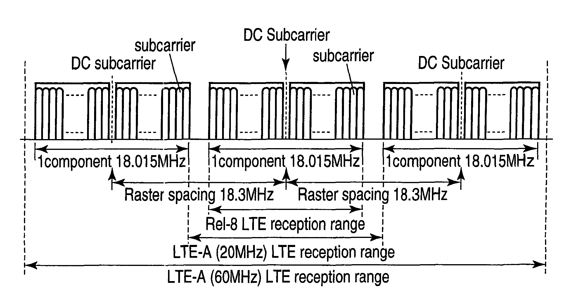
[0027]A wireless communication system according to the present invention will be described by exemplifying a cellular system using OFDM in the downlink. This wireless communication system includes mobile wireless terminals and a wireless base station and performs wireless communication using OFDM in the downlink transmitted from the wireless base station and received by the mobile wireless terminals. There are two types of mobile wireless terminals, i.e., a type x conforming to Rel-8 LTE and a type y conforming to LTE-Advanced (LTE-A). The wireless base station transmits signals to a plurality of mobile wireless terminals of type x and a plurality of mobile wireless terminals of type y.

[0028]The maximum receivable bandwidth of the mobile wireless terminal of type x is one component (18.015 MHz). The maximum receivable bandwidth of the mobile wireless terminal of type y inclu...


PUM


Abstract

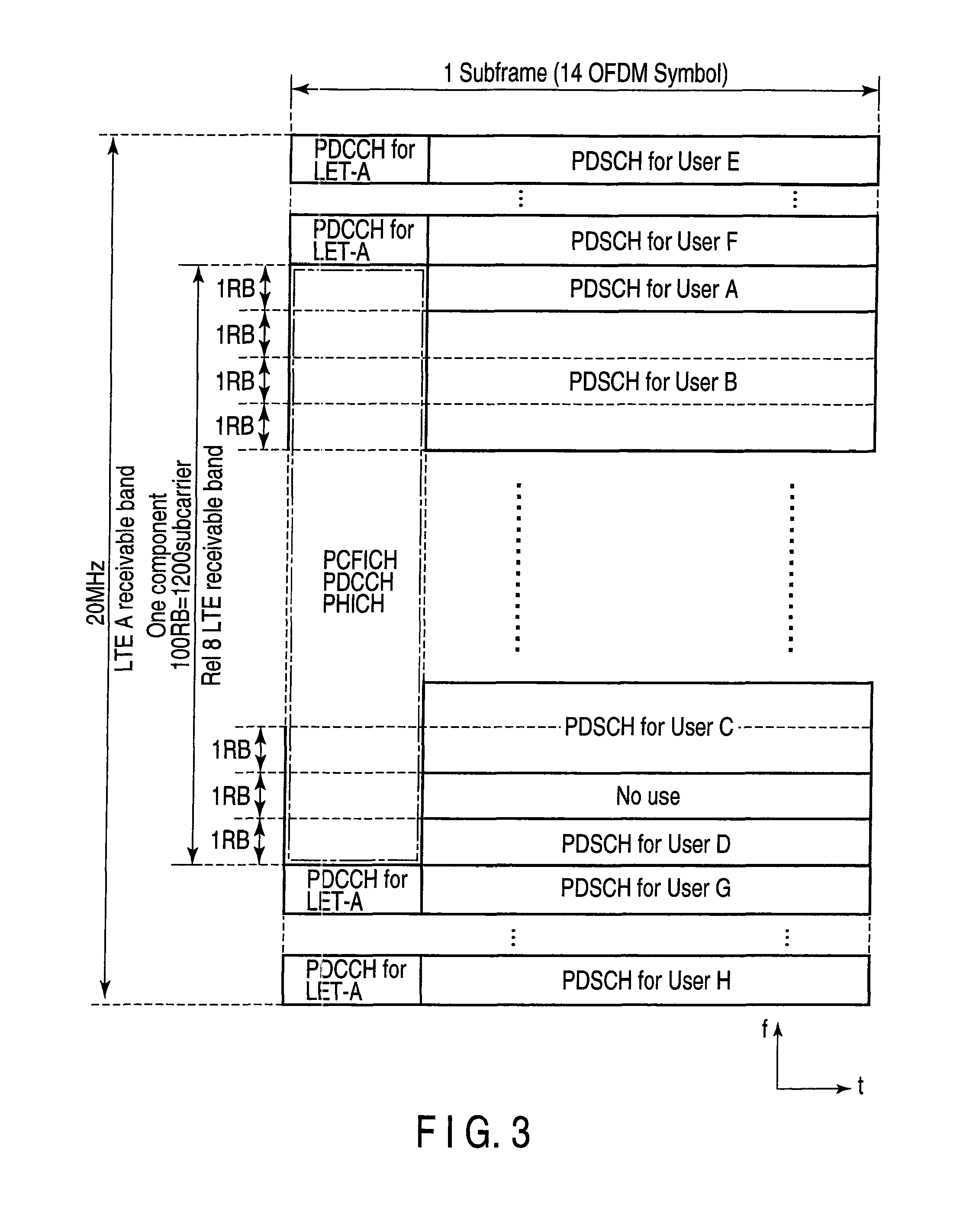
A wireless base station apparatus assigns channels to a narrowband mobile wireless terminal apparatus of type x (Rel-3 LTE) within the range of one component as its standard and assigns, to a broadband mobile wireless terminal apparatus of type y (LTE-A), channels not only within the range of one component but also channels in other components or between components.

Description

CROSS-REFERENCE TO RELATED APPLICATIONS[0001]This application is based upon and claims the benefit of priority from prior Japanese Patent Application No. 2009-063249, filed Mar. 16, 2009, the entire contents of which are incorporated herein by reference.BACKGROUND OF THE INVENTION[0002]1. Field of the Invention[0003]The present invention relates to communication between a wireless base station apparatus and a mobile wireless terminal apparatus which are accommodated in a network.[0004]2. Description of the Related Art[0005]A mobile communication system such as a cellular system uses various parameters for defining the transmission / reception capability of a terminal to support terminals of various application purposes (e.g., 3GPP (3rd Generation Partnership Project) TS 36.306 V8.2.0 (2008 05)). Combinations of parameters define UE categories. Terminal capabilities (UE capabilities) that define the UE categories include a maximum information transmission rate which is defined on each ...

Claims


Application Information

Patent Timeline
Patent Type & Authority Patents(United States)
IPC IPC(8): H04J1/16
CPCH04W72/042H04L5/0053H04L5/001H04L27/2601H04L5/0094H04L5/0044H04W72/23
Inventor ASANUMA, YUTAKA
Owner FUJITSU TOSHIBA MOBILE COMM LTD
Learn More