
Surgical instrument for joining tissue

a surgical instrument and tissue technology, applied in the direction of surgical staples, surgical forceps, paper/cardboard containers, etc., to achieve the effect of facilitating remote approximation of the first and second jaw members

Active Publication Date: 2012-12-11
TYCO HEALTHCARE GRP LP
View PDF247 Cites 1527 Cited by
  • Summary
  • Abstract
  • Description
  • Claims
  • Application Information

AI Technical Summary

Benefits of technology

The present disclosure provides a surgical instrument with a handle assembly and an elongated portion that extends distally from the handle assembly. The instrument has an end effector with a first jaw member and a second jaw member that are pivotably movable with respect to each other. The instrument also includes an actuation assembly that is mechanically cooperative with the end effector and can move the jaw members between a first position where they are spaced from each other and a second position where they are in an approximated position. The instrument can be used in minimally invasive or laparoscopic surgery and has a loading unit that can be connected to the end effector for use. The instrument can also have a cam slot and cam pin configuration to facilitate remote approximation of the jaw members and an approximation member to cause the end effector to move towards its second position. The end effector can also be movable between a parallel position and an offset position. The technical effects of the present disclosure include improved surgical instrumentation for joining tissue with staples and a compact design for easy handling and use in minimally invasive or laparoscopic surgery.

Problems solved by technology

When the shaft of the surgical instruments is bent or articulated, there may exist practical challenges associated with a translation force required to translate the sled along the shaft during the firing sequence.
Likewise, when the shaft of the electrosurgical forceps is bent or articulated, there may exist practical challenges associated with a translation force required to translate the knife blade within the knife slot after tissue has been electrosurgically treated.

Method used


Image

  • Surgical instrument for joining tissue
  • Surgical instrument for joining tissue
  • Surgical instrument for joining tissue

Examples


Embodiment Construction

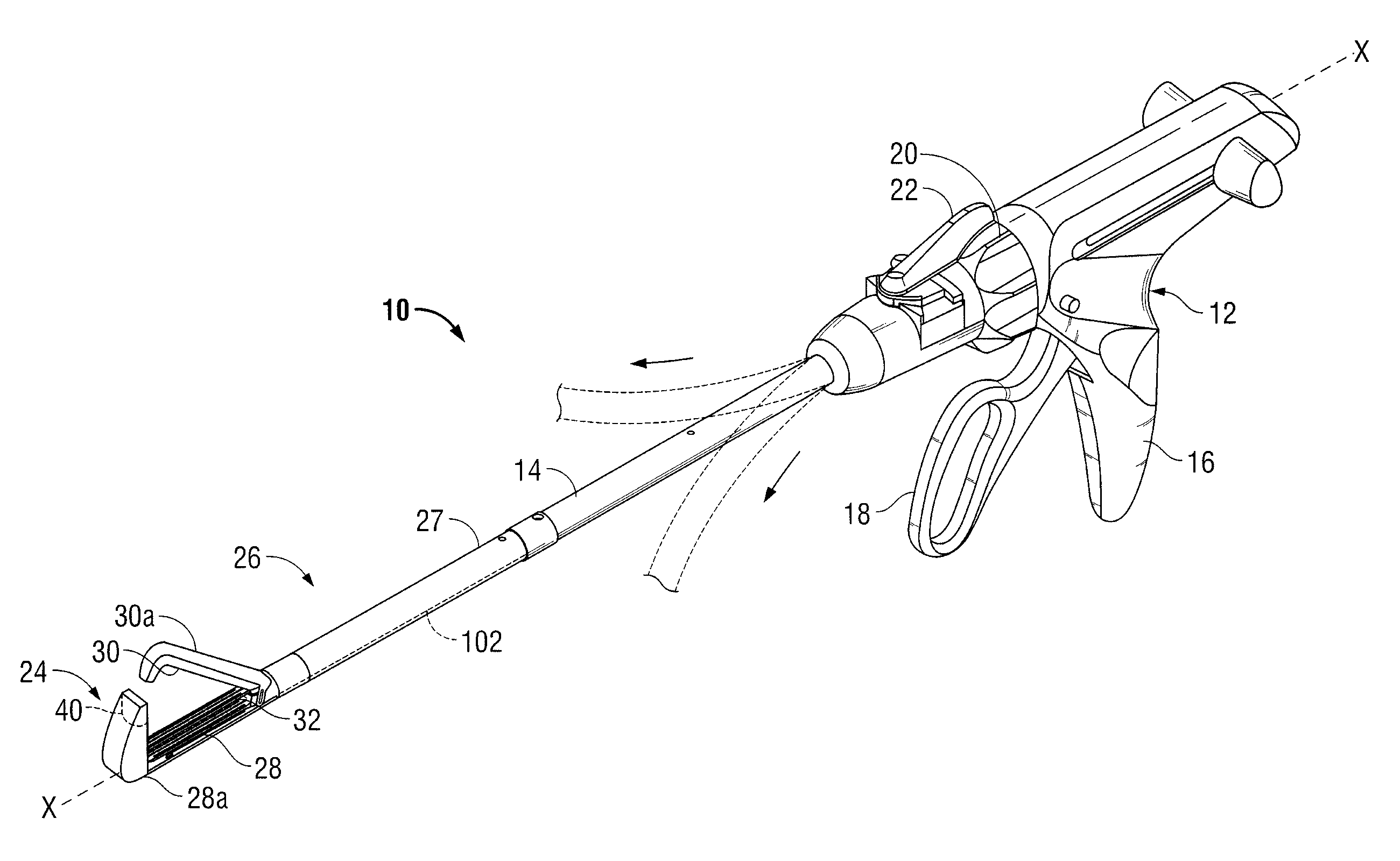
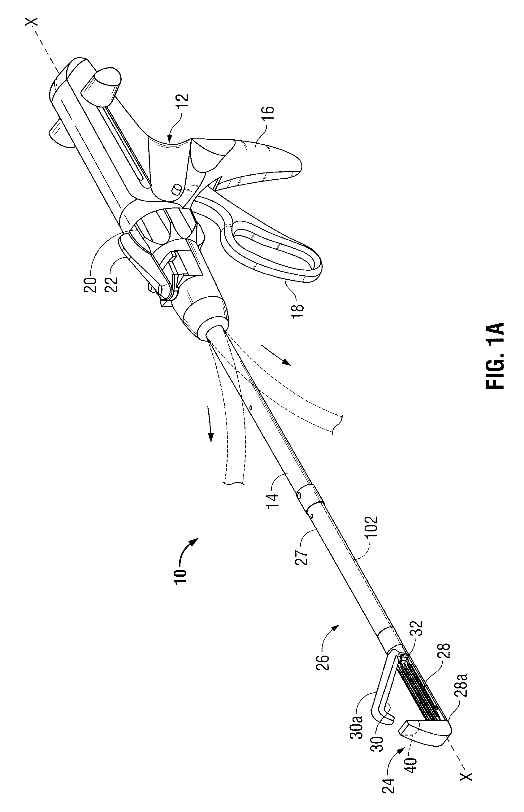
[0039]Embodiments of the presently disclosed surgical instrument are described in detail with reference to the drawings, wherein like reference numerals designate similar or identical elements in each of the several views. In the drawings and the description that follows, the term “proximal” refers to the end of the surgical stapling instrument that is closest to the handle assembly, whereas the term “distal” refers to the end of the surgical stapling instrument that is farthest from the handle assembly. As appreciated by one skilled in the art, the depicted surgical stapling instrument fires staples, but it may be adapted to fire any other suitable fastener such as clips and two-part fasteners.

[0040]FIG. 1A illustrates one type of surgical stapling instrument that may be employed with an actuation assembly 100 (FIG. 2A-2C) of the present disclosure. Briefly, surgical stapling instrument 10 includes a handle assembly 12 and an elongated body or shaft 14. Shaft 14 defines a longitudi...


PUM

PropertyMeasurementUnit
mechanicalaaaaaaaaaa
electrical energyaaaaaaaaaa
translation forceaaaaaaaaaa

Abstract

A surgical instrument for surgically joining tissue is provided. The surgical instrument includes a handle assembly that includes an actuator member. An end effector is operatively disposed adjacent a distal portion of an elongated shaft of the surgical instrument. The end effector includes a first jaw member pivotably disposed with respect to a second jaw member. The end effector is movable between a first position where the jaw members are spaced from one another, and a second position where the jaw members are in an approximated position. Each of the first and second jaw members includes a respective longitudinal track. An actuation assembly is disposed in mechanical cooperation with the end effector, wherein actuation of the actuation member causes the actuation assembly to translate from a distal portion of the end effector towards a proximal portion of the end effector through the tracks in the first and second jaw members.

Description

BACKGROUND[0001]1. Technical field[0002]This application relates to surgical instruments for joining tissue, and more particularly, to surgical instruments that are pull activated for sequentially applying a plurality of surgical fasteners to body tissue and to electrosurgical instruments that are configured to sever tissue after tissue has been electrosurgically treated.[0003]2. Background of Related Art[0004]Surgical instruments wherein tissue is first grasped or clamped between opposing jaw structure and then joined by surgical fasteners, or other suitable means, are well known in the art. Instruments for this purpose can include two elongated members which are respectively used to capture or clamp tissue. Typically, such surgical instruments include a shaft extending from a handle and / or trigger assembly, an end effector assembly, which includes an anvil assembly and a cartridge assembly for supporting a plurality of surgical fasteners, an approximation mechanism for approximati...

Claims


Application Information

Patent Timeline
Patent Type & Authority Patents(United States)
IPC IPC(8): A61B17/072
CPCA61B17/07207A61B18/085A61B17/068A61B2017/07285A61B2017/2939A61B2017/2947A61B2017/2946
Inventor KASVIKIS, DINO
Owner TYCO HEALTHCARE GRP LP
Learn More