Clamp adapter assembly

a technology of adapter and clamping rod, which is applied in the direction of snap fasteners, buckles, mechanical equipment, etc., can solve the problems of time-consuming, broken bolts, and inability to quickly remove, exchange or replace instruments

Active Publication Date: 2012-12-11
SRM
View PDF10 Cites 17 Cited by
  • Summary
  • Abstract
  • Description
  • Claims
  • Application Information

AI Technical Summary

Problems solved by technology

However, these bolted split ring connections have several drawbacks.
The first problem relates to their inability for allowing instrumentation to be quickly removed, exchanged or replaced.
This can be a time consuming task.
Second, in removing the nuts or bolts, occasionally the operator will inadvertently “strip” the threads within the base or the bolts extending from the base.
Replacing such a base in a pressure vessel may require the skill of an ASME-certified welder and can cost tens of thousands of dollars.
Additionally, if the pressure vessel contains any product therein, the product is often times worth hundreds of thousands of dollars and may have to be discarded.
A further shortcoming of the split ring connection occurs when an operator drops or misplaces the nuts or bolts, requiring yet additional time and effort to retrieve or replace the nuts or bolts.
Split rings are often necessary because a solid retaining ring is not able to be installed over existing instrumentation.
The split ring's increased thickness sometimes presents clearance issues with the instrumentation held in place by the split ring.
The spacer tube of the dead leg introduces a recessed area in the interior surface of the vessel that is difficult to clean thoroughly.
Because it is difficult to visually inspect and direct cleaning solutions into dead legs, contaminants can remain present even after the interior of the vessel is thought to be clean.
This is especially worrisome in industries with strict sanitary requirements, or that have elevated legal liability if their products contain impurities, such as the pharmaceutical, food and beverage, or chemical industries.
However, the dead legs often associated with such connections can cause cleanliness and sterility issues.
The task of replacing a base configured for a utilizing split ring connection with a base or dead leg configured for utilizing a tri-clamp connection is a substantial undertaking that may require the skill of an ASME-certified welder and can cost tens of thousands of dollars.
Furthermore, the bases designed for utilizing split ring connections do not generally have the shortcomings of the dead legs configured for utilizing tri-clamp connections.

Method used


Image

  • Clamp adapter assembly
  • Clamp adapter assembly
  • Clamp adapter assembly

Examples


Embodiment Construction

[0020]The following detailed description of the invention references the accompanying drawing figures that illustrate specific embodiments in which the invention can be practiced. The embodiments are intended to describe aspects of the invention in sufficient detail to enable those skilled in the art to practice the invention. Other embodiments can be utilized and changes can be made without departing from the scope of the present invention. The present invention is defined by the appended claims and the description is, therefore, not to be taken in a limiting sense and shall not limit the scope of equivalents to which such claims are entitled.

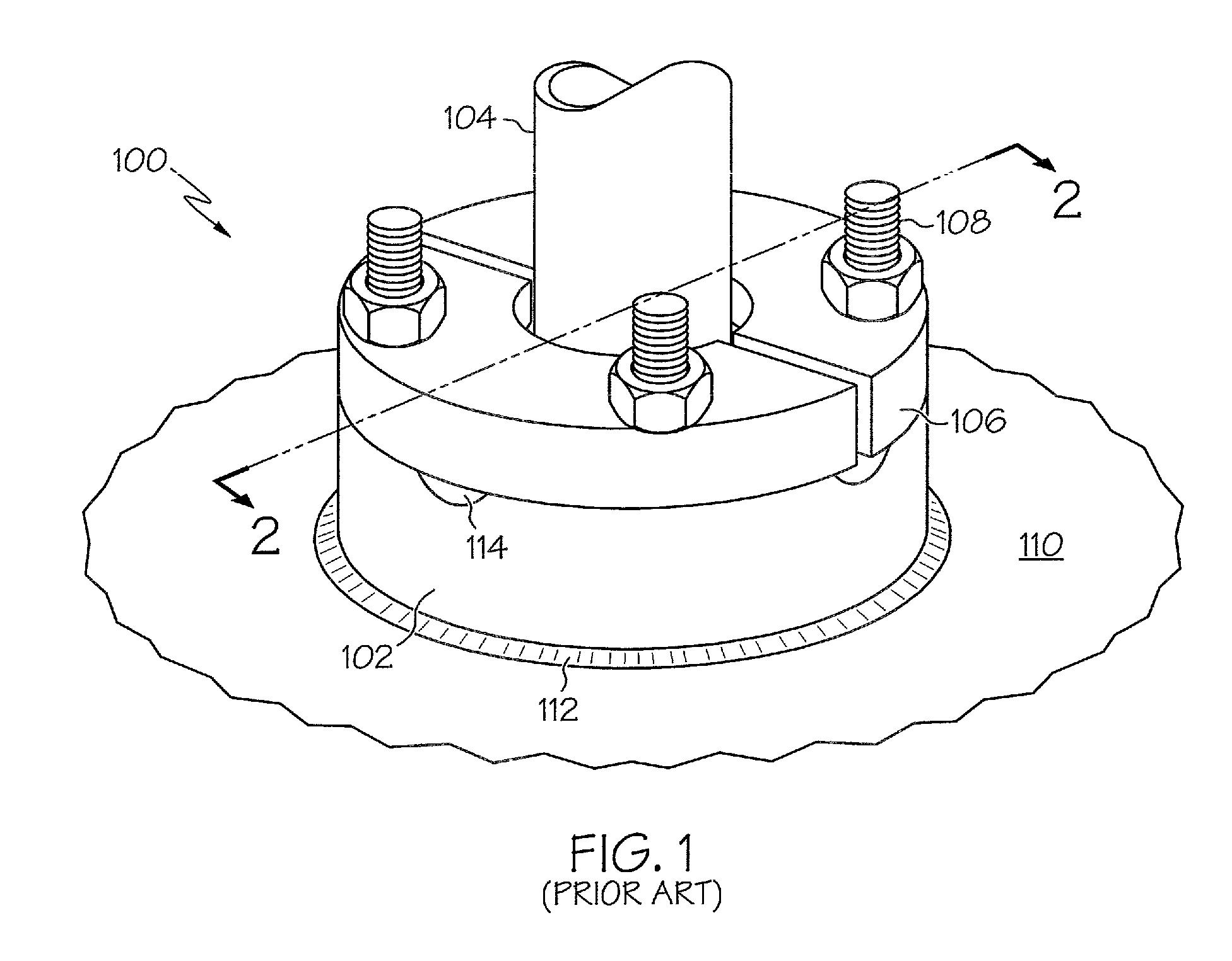
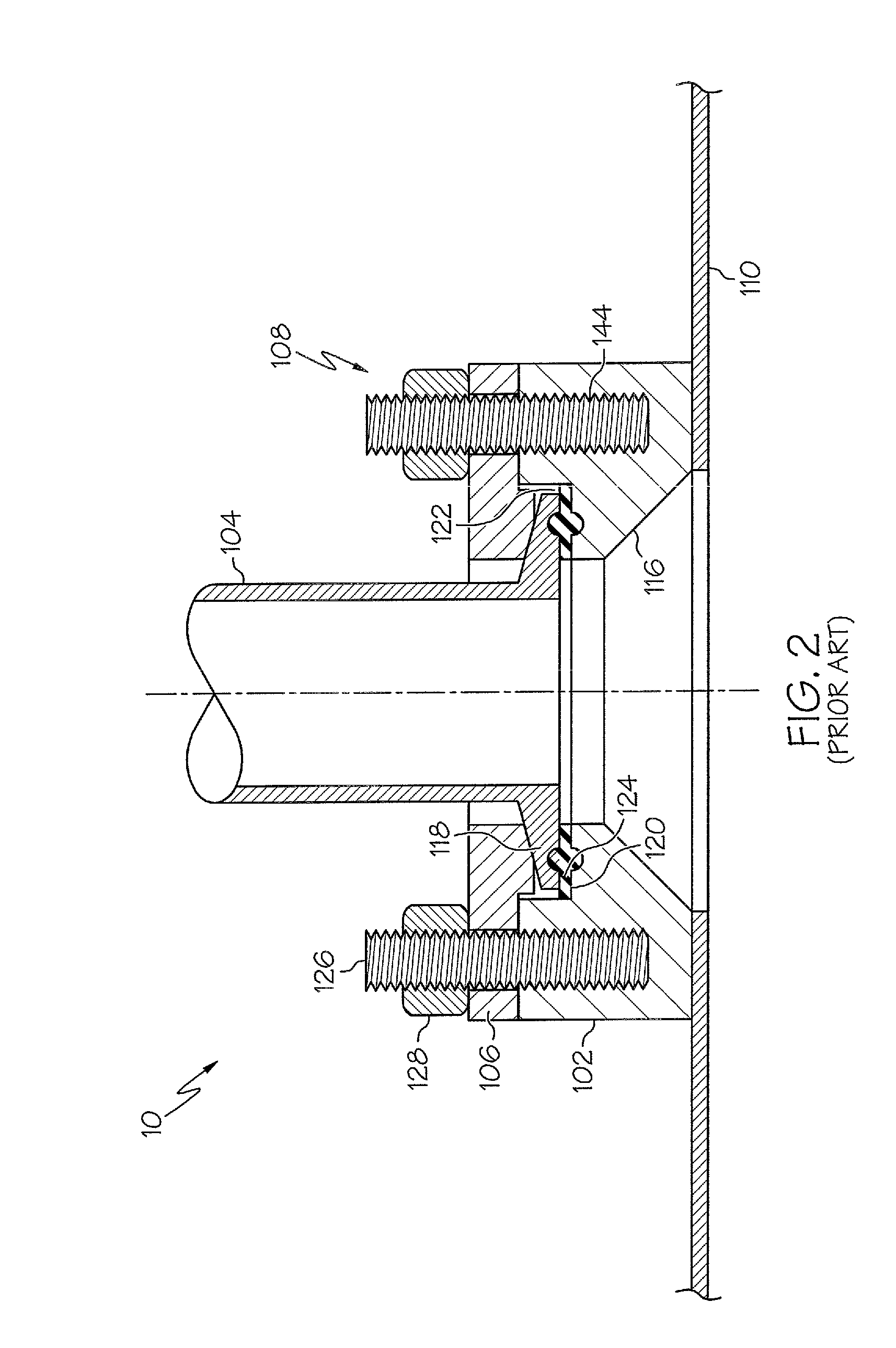
[0021]Turning now to the drawing figures, FIG. 1 shows an embodiment of a prior art bolted connection assembly 100 that includes a bolt connection base 102, a device or instrument 104, a bolted retaining ring 106, and threaded fasteners 108. As illustrated in FIG. 1, retaining ring 106 is split into two independent sections. These independent ...


PUM


Abstract

A clamp adapter assembly for connecting an instrument to a pressure vessel. The clamp adapter assembly allows an operator to convert a bolt connection base known in the art into a base suitable for utilizing a clamped connection similarly known in the art. The connection assembly includes a bottom plate, at least one fastener to fasten the bottom plate to a base, a top retaining plate, and a clamp. The peripheral portions of the bottom plate and top retaining plate may be beveled in order to be received within a tri-clamp. The top retaining plate may include two sections that overlappingly engage one another.

Description

CROSS-REFERENCE TO RELATED APPLICATIONS[0001]This nonprovisional application claims the benefit of Provisional Patent Application Ser. No. 61 / 159,506 filed Mar. 12, 2009, the entire disclosure of which is incorporated herein by reference.BACKGROUND OF THE INVENTION[0002]Pressure vessels are utilized in many industries for manufacturing products when maintaining specific temperatures and pressures is required. Industries using pressure vessels include but are not limited to pharmaceutical, chemical, food and beverage, medical, biotechnical, ethanol, dairy, water treatment, paper, cryogenic, and other industries requiring chemical or biological processing in a pressurized environment. The processes that require the use of pressure vessels often require devices or other instrumentation to measure and control operating conditions such as temperature, pressure, liquid level, and other parameters through various known instrumentation. Further, these industries may also require pressure ve...

Claims


Application Information

Patent Timeline
Patent Type & Authority Patents(United States)
IPC IPC(8): F16L23/00
CPCB01J3/002B01J3/03F16L23/10F16L23/0283Y10T24/44017
Inventor GAYER, JASONMCKEE, CHARLES P.JOHNSON, CARL
Owner SRM
Why Eureka
Try Eureka