Lamp having mounting slot

a lamp and mounting bracket technology, applied in the field of lamps, can solve the problems of increasing the the amount of lamps is not changed according to the amount of lamps, and the use of the lamp holder increases the total cost and complexity and achieves the effect of low total cost of disposing the lamp

Inactive Publication Date: 2012-12-11
LIN CHIU MIN
View PDF8 Cites 34 Cited by
  • Summary
  • Abstract
  • Description
  • Claims
  • Application Information

AI Technical Summary

Benefits of technology

[0008]A guide rail or a pair of resilient plates is disposed at a presupposed position and is mounted through the slot of the lamp to hold the lamp. An amount of lamps held on the guide rail or the pair of resilient plates is changeable according to needful brightness. Therefore, disposing the lamp is easy, quick and convenient, and a total cost for disposing the lamp is low.

Problems solved by technology

However, usage of the lamp holder increases total cost and complexity of disposing the lamp.
Moreover, since the lamp holder is set up at the specific position and only allows for mounting a specific amount of lamps, the amount of lamps is not changed according to needs for brightness.

Method used


Image

  • Lamp having mounting slot
  • Lamp having mounting slot
  • Lamp having mounting slot

Examples


Embodiment Construction

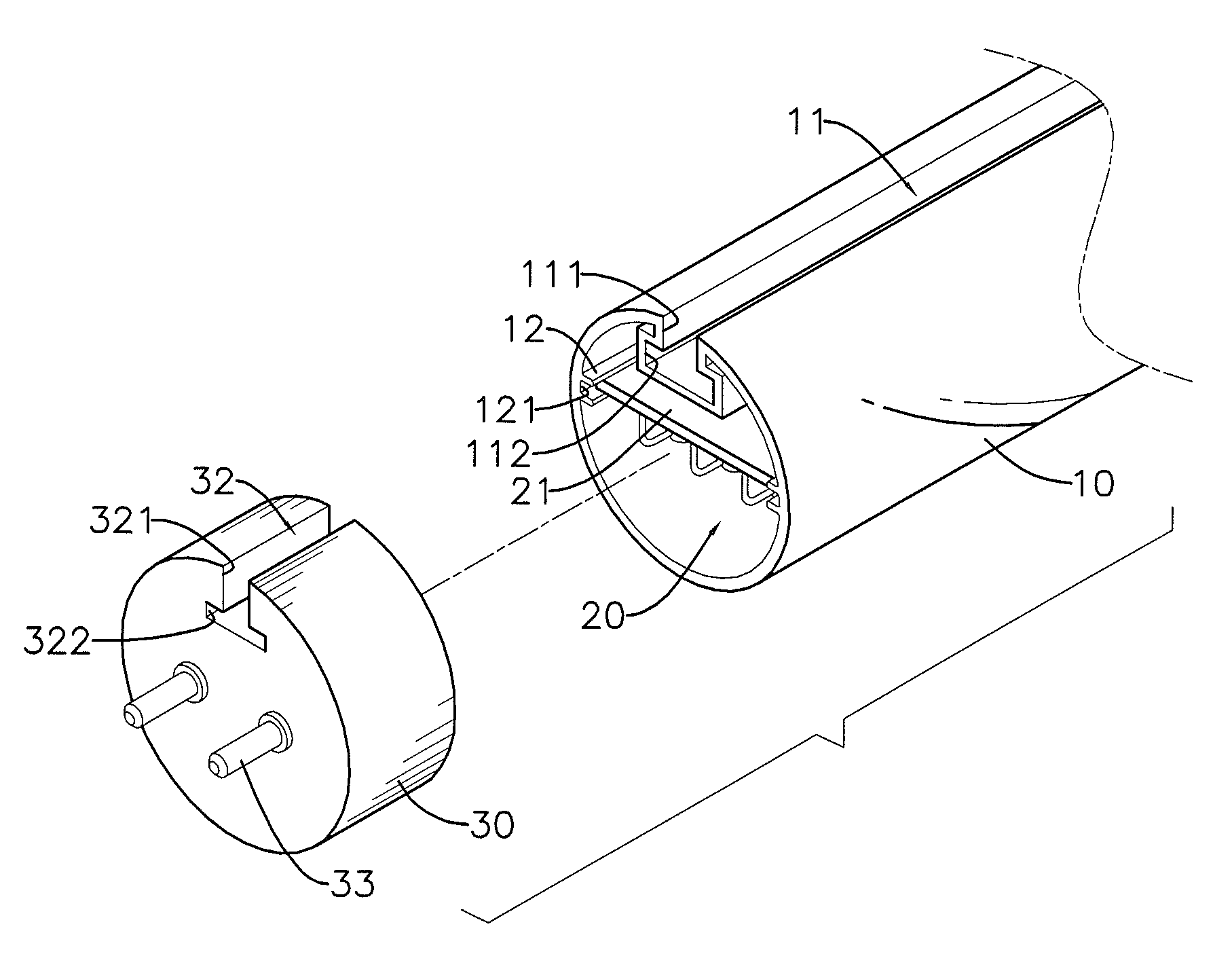
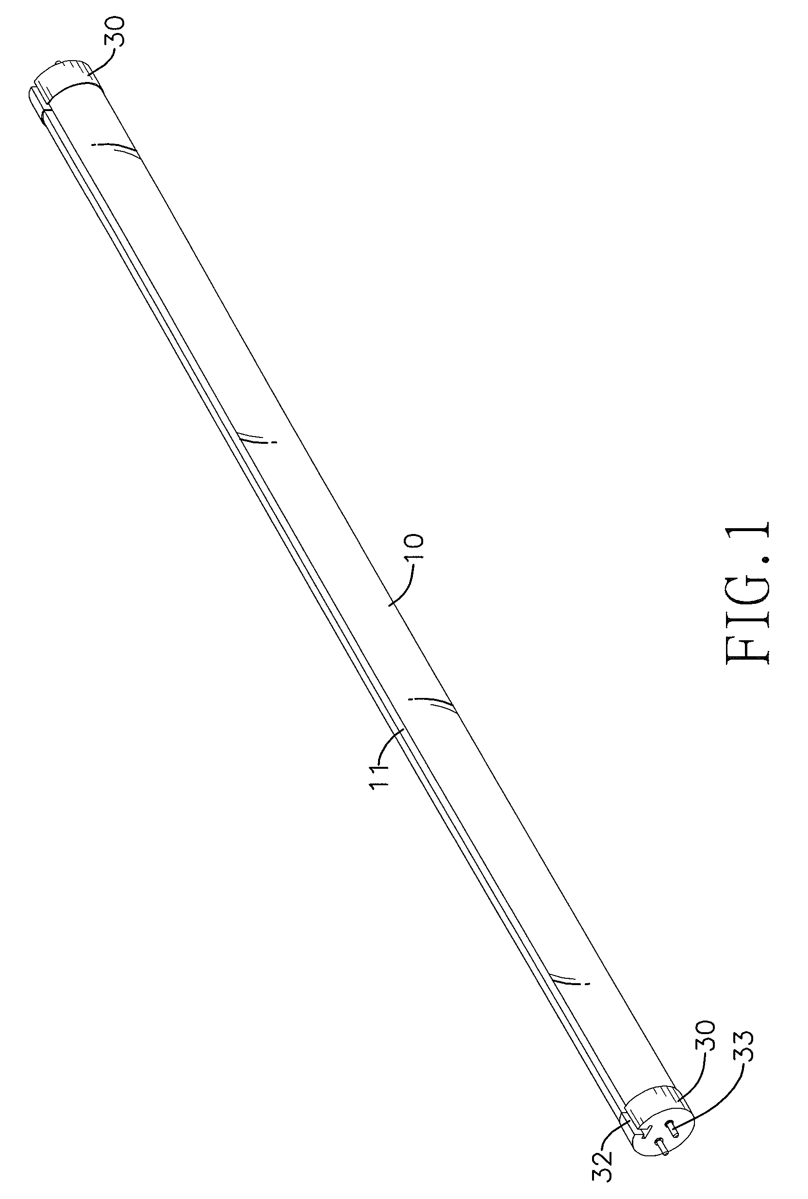
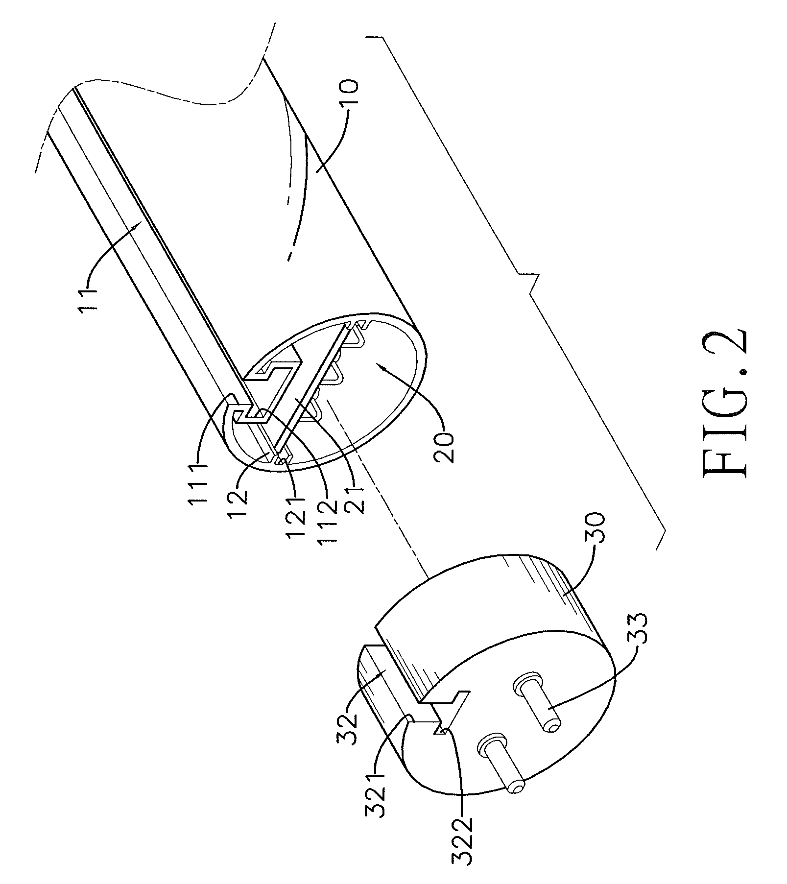
[0014]With reference to FIGS. 1 and 2, a lamp in accordance with the present invention comprises a light tube 10, an illuminant module 20 and two end caps 30.

[0015]The light tube 10 is tubular and elongated and has a main slot 11 and two tracks 12.

[0016]The main slot 11 is substantially inverted T-shaped in cross-section, is formed in and axially along an outer surface of the light tube 10, is formed through two opposite ends of the light tube 10 and has a mounting recess 111 and two positioning recesses 112. The mounting recess 111 of the main slot 11 is formed in the outer surface of the light tube 10 and having two opposite mounting surfaces. The positioning recesses 112 of the main slot 11 are formed respectively in the mounting surfaces of the mounting recess 111 of the main slot 11.

[0017]The tracks 12 are formed on and axially along the inner surface of the light tube 10. Each track 12 has an engaging recess 121 formed along the track 12 and corresponding to the engaging reces...


PUM


Abstract

A lamp has a light tube, an illuminant module mounted in the light tube and two end caps mounted respectively on two opposite ends of the light tube. A slot, being substantially inverted T-shaped in cross-section, is formed in and axially along the light tube and the end caps. A guide rail or a pair of resilient plates is disposed at a presupposed position and is mounted through the slot of the lamp to hold the lamp. An amount of lamps held on the guide rail or the pair of resilient plates is changeable according to needful brightness. Therefore, disposing the lamp is easy, quick and convenient, and a total cost for disposing the lamp is low.

Description

BACKGROUND OF THE INVENTION[0001]1. Field of the Invention[0002]The present invention relates to a lamp and, especially, to a lamp that has a mounting slot and is easily set up at a specific position.[0003]2. Description of the Prior Art(s)[0004]A conventional lamp must be used with a lamp holder. The lamp holder is set up at a specific position of a ceiling or a wall in advance, and, then the conventional lamp is mounted onto the lamp holder.[0005]However, usage of the lamp holder increases total cost and complexity of disposing the lamp. Moreover, since the lamp holder is set up at the specific position and only allows for mounting a specific amount of lamps, the amount of lamps is not changed according to needs for brightness.[0006]To overcome the shortcomings, the present invention provides a lamp having a mounting slot to mitigate or obviate the aforementioned problems.SUMMARY OF THE INVENTION[0007]The main objective of the present invention is to provide a lamp having a mounti...

Claims


Application Information

Patent Timeline
Patent Type & Authority Patents(United States)
IPC IPC(8): F21V21/00
CPCF21K9/17F21V3/02F21V19/009F21V19/0045F21V19/04F21Y2101/02F21Y2115/10F21K9/275F21K9/272F21K9/27
Inventor LIN, CHIU-MIN
Owner LIN CHIU MIN
Why Eureka
Try Eureka