Deep insertion vented earpiece system

Active Publication Date: 2012-12-18
GOVERNMENT OF THE UNITED STATES AS REPRESENTED BY THE SEC OF THE AIR FORCE
View PDF40 Cites 10 Cited by
  • Summary
  • Abstract
  • Description
  • Claims
  • Application Information

AI Technical Summary

Benefits of technology

[0017]In accordance with the foregoing principles and objects of the invention, a deep insertion vented earpiece system is described. The deep insertion vented earpiece system includes a pair of deep fitting resilient earpieces custom sized and manufactured to fit the contours of the wearer's ear canals exactly (from impressions of the wearer's ears), to enhance comfort and maximize the attenuation of ambient noise. The earpieces are manufactured from silicone or other compliant, hypo-allergenic material and are cast from a custom mold made of the wearer's ear by techniques known to those having ordinary skill in the art. As used throughout, the term “deep fitting” or “deep insertion” pertains to custom fitted earpieces manufactured to be inserted such that the tip of the device rests against the second bend of the external ear canal. This deep insertion aspect of our invention represents a dramatic departure from the prior art earpieces that are made to be inserted to the first bend of the ear canal. Advantageously, this deep insertion feature of our invention has been demonstrated by extensive testing to provide superior noise reduction over the prior art earpieces.
[0018]The deep insertion vented earpiece syst

Problems solved by technology

While these earpiece systems are in widespread use, they are not without the need for improvement.
For example, the resilient foam provides only a limited degree of conformity to the contours of the wearer's ear canal.
During use, the earpieces can become uncomfortable and they also tend to fall out.
Additionally, the tendency of the wearer during removal of the earpieces is to pull on the audio cables rather than on the earpieces themselves, causing the audio cables to stretch, pull out or otherwise compromise the integrity of the earpiec

Method used


Image

  • Deep insertion vented earpiece system
  • Deep insertion vented earpiece system
  • Deep insertion vented earpiece system

Examples


Embodiment Construction

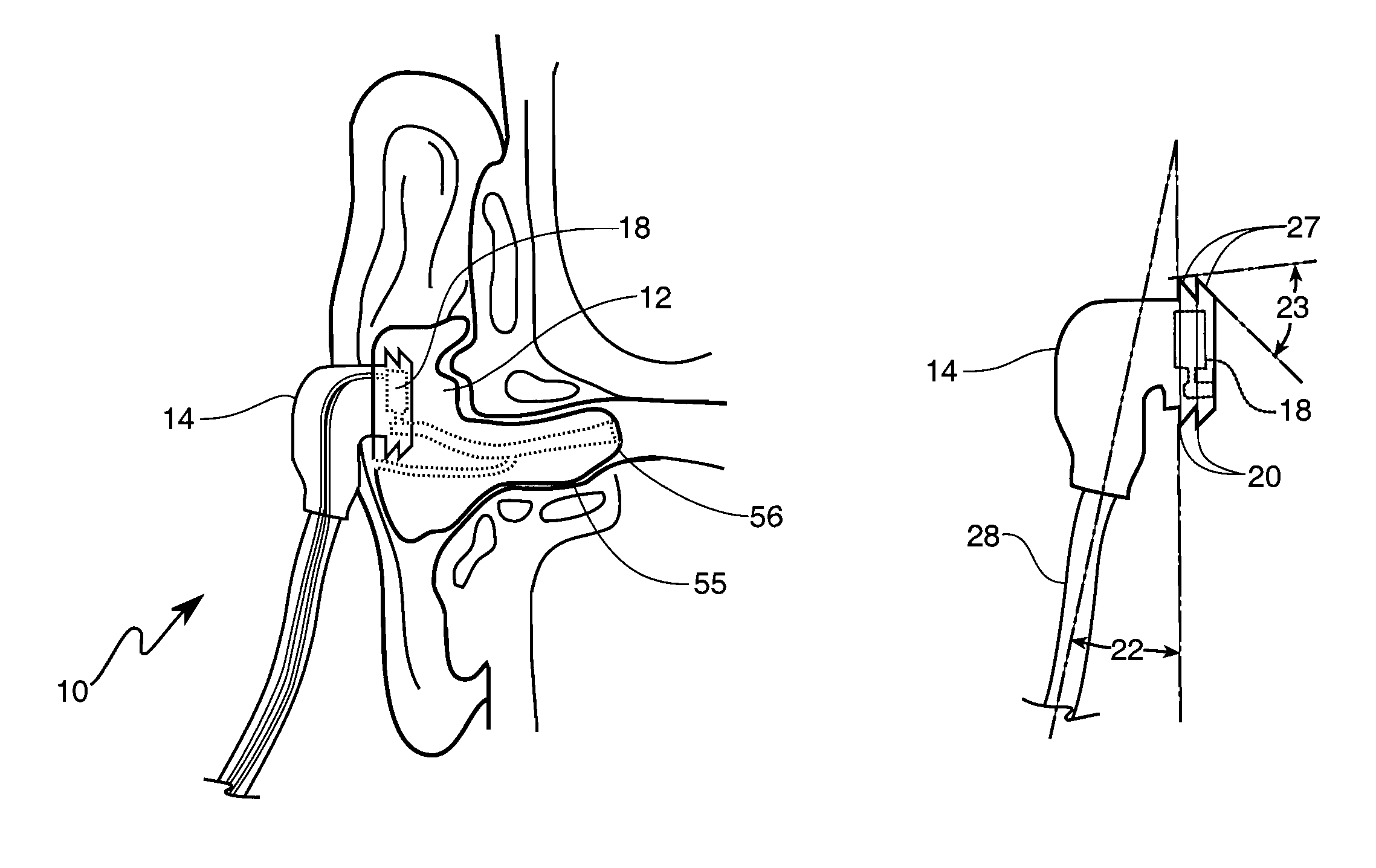
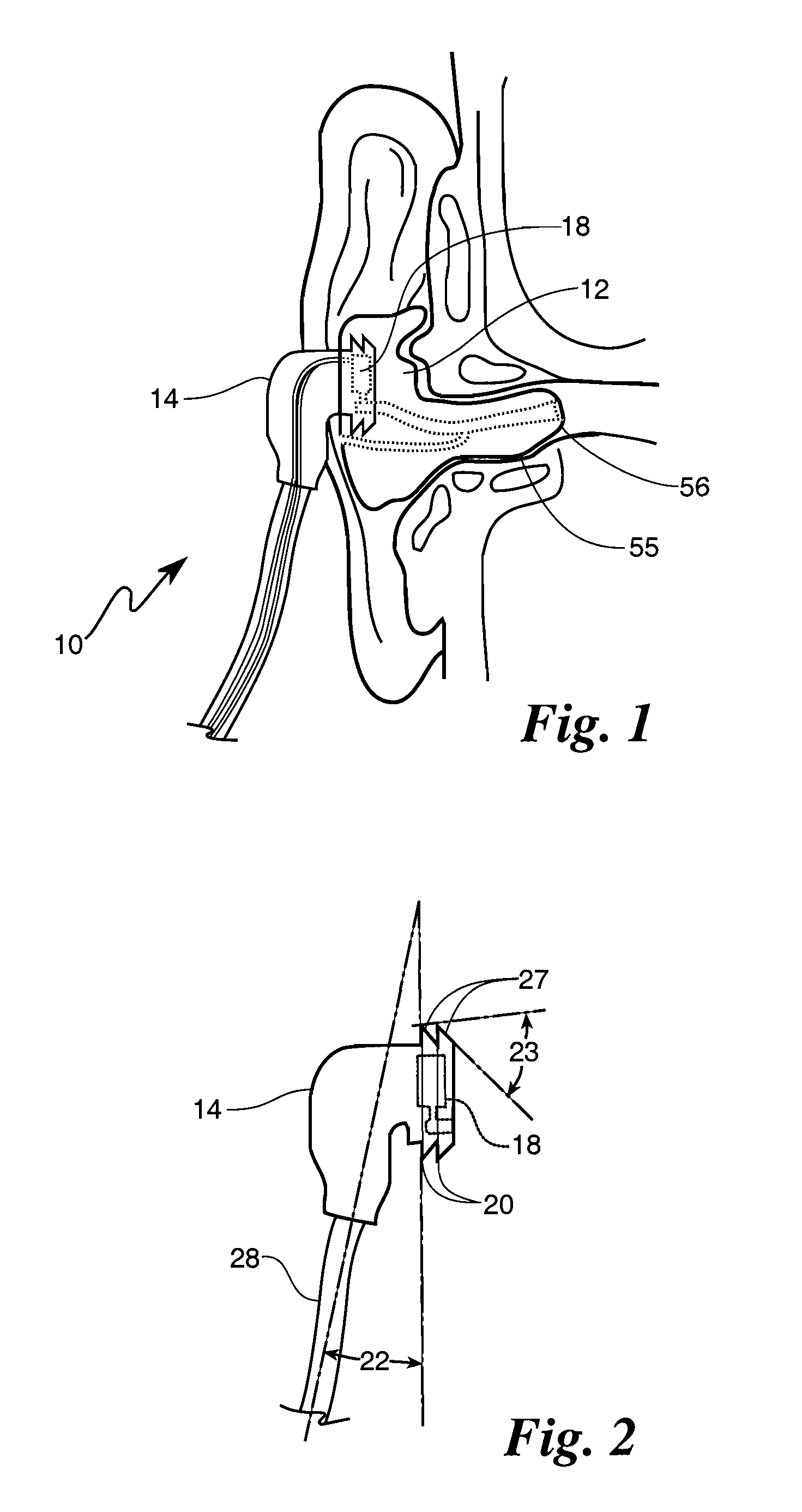
[0028]Reference is made to FIG. 1, showing a portion of the deep insertion vented earpiece system 10 of the present invention placed within the ear of a wearer. As will be described in more detail below, the deep insertion vented earpiece system 10 includes a pair of resilient, fitted earpieces 12 adapted to be worn within the ear. The earpieces 12 are custom sized and manufactured to fit the contours of the wearer's ear canals exactly (from impressions of the wearer's ears), to enhance comfort and maximize the attenuation of ambient noise. The earpieces 12 are manufactured from silicone or other compliant, hypo-allergenic material and are cast from a custom mold made of the wearer's ear by techniques known to those having ordinary skill in the art.

[0029]As used throughout and shown in FIG. 6, the term “deep fitting” or “deep insertion” pertains to custom fitted earpieces 12 manufactured to be inserted such that a tip T of the device rests against a second bend 56 of an external ear...


PUM


Abstract

A deep insertion vented earpiece system is described including resilient earpieces shaped to a wearer's ear canal for a conformal fit. A receptacle is provided within the outer surface of each earpiece for releasably receiving an audio plug. The audio plugs include a miniature loudspeaker and a pair of external ribs for mating with a corresponding pair of grooves formed along the periphery of the receptacle. This rib and groove feature provides for a secure retention of the audio plugs while enabling a simple removal operation. Each earpiece includes an audio passage to conduct the audio signal from the loudspeaker and a vent passage to enable continuous venting of the wearer's ear to atmosphere.

Description

CROSS REFERENCE TO RELATED APPLICATIONS[0001]The present application is a continuation-in-part of U.S. patent application Ser. No. 11 / 417,281, filed on Apr. 24, 2006 now U.S. Pat. No. 7,784,583, by inventors John A. Hall, et al., entitled “Deep Insertion Vented Earpiece System,” which claims priority to Provisional Application No. 60 / 675,437, filed Apr. 25, 2005, entitled “Vented Earpiece System.”RIGHTS OF THE GOVERNMENT[0002]This invention was made in the performance of a Cooperative Research and Development Agreement with the Department of the Air Force. The Government of the United States has certain rights to use the invention.BACKGROUND OF THE INVENTION[0003]The present invention relates generally to personal audio / hearing protection devices and more specifically to a modular earpiece system for connection to external radios, intercom systems and the like adapted to be worn deep in the ear of the wearer, to the second bend of the ear canal.[0004]The desirability of personal aud...

Claims


Application Information

Patent Timeline
IPC IPC(8): H04R25/02H04R25/00
CPCH04R1/1016
Inventor HALL, JOHN A.CARTWRIGHT, KARLCARTWRIGHT, KRIS
Owner GOVERNMENT OF THE UNITED STATES AS REPRESENTED BY THE SEC OF THE AIR FORCE
Why Eureka
Try Eureka