
Image-driving method and driving circuit of display and display apparatus

a technology of driving circuit and display apparatus, applied in the field of image display technique, can solve the problems of large memory capacity, large access requirements, and blurred motion images

Inactive Publication Date: 2012-12-18
NOVATEK MICROELECTRONICS CORP
View PDF8 Cites 1 Cited by
  • Summary
  • Abstract
  • Description
  • Claims
  • Application Information

AI Technical Summary

Benefits of technology

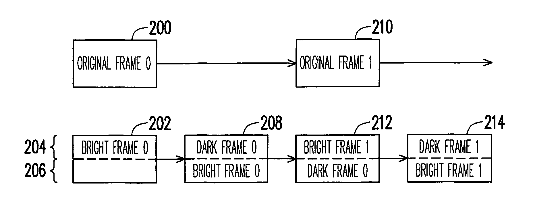
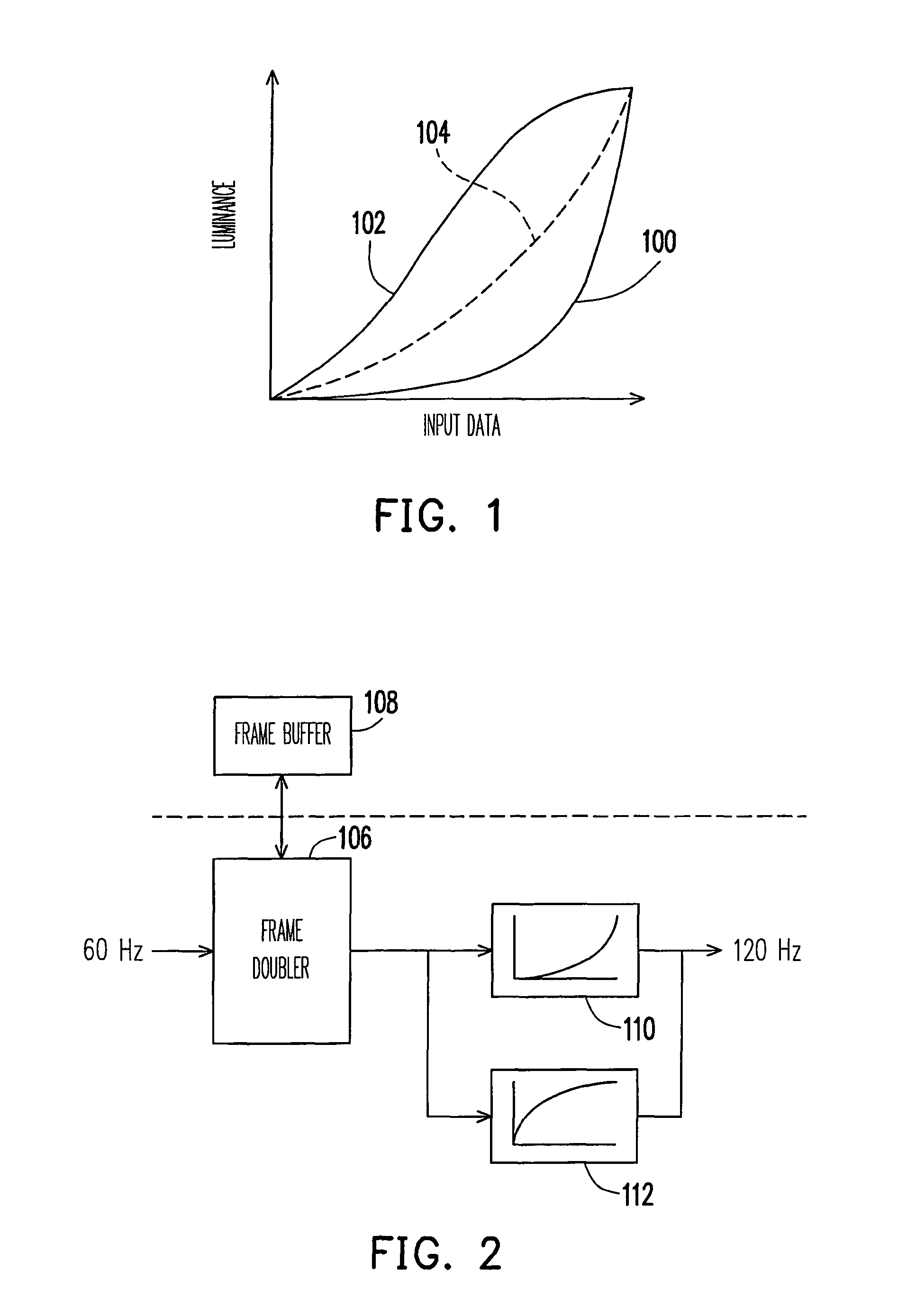
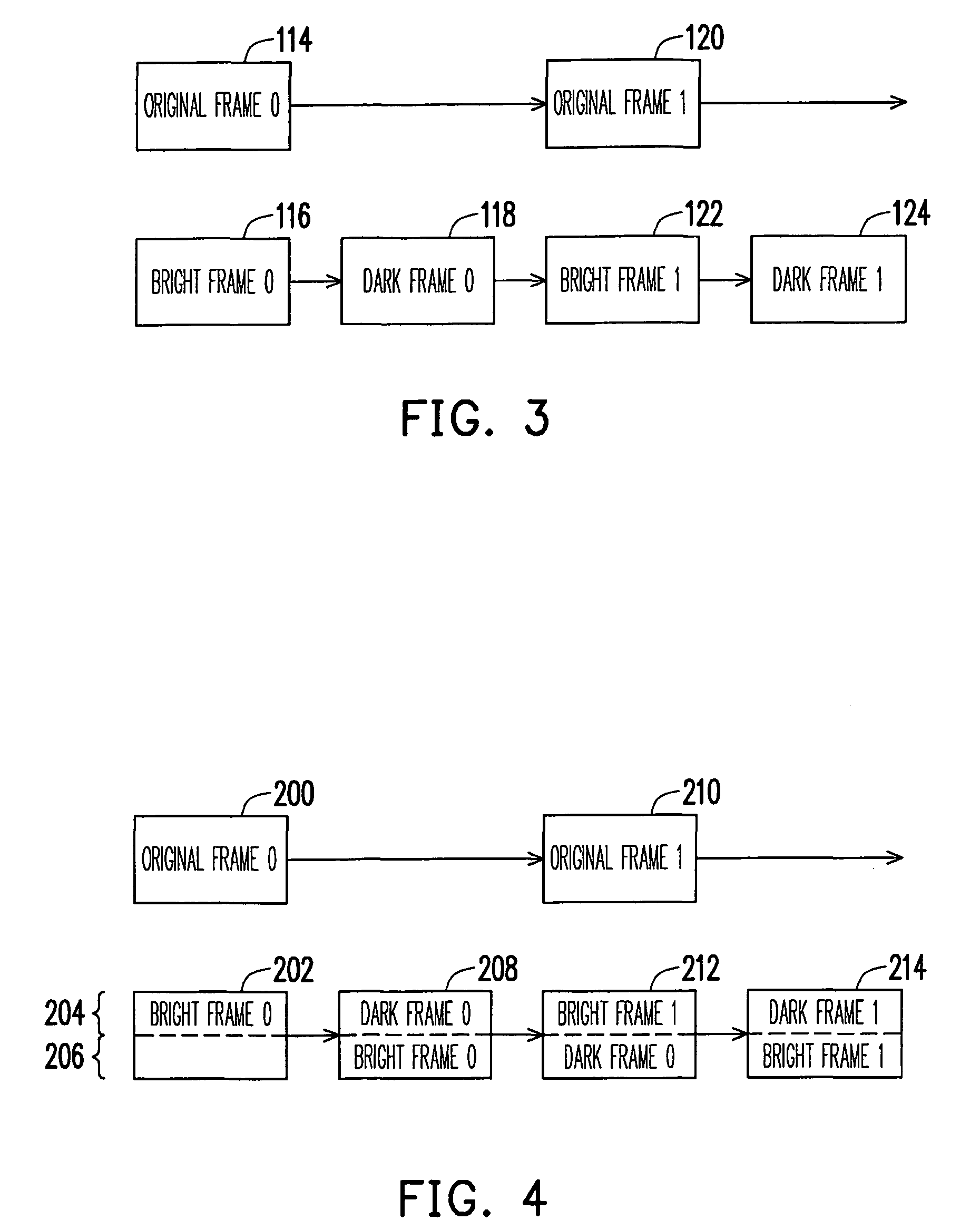
The present invention provides an image-driving method and circuit for a display that can solve the problem of excessive access bandwidth and memory capacity. The method involves registering a post-part image frame of a previous image frame and producing two display frames, one for sequentially displaying the prior-part image frame and the other for displaying the post-part image frame. The method also includes conducting a first luminance adjustment on the prior-part image frame and the post-part image frame to take the first part of the image frame and the second part of the image frame, respectively. The circuit includes a frame buffer, a frame douler, and two luminance adjustment units to implement the method. The technical effects of the invention include reducing the amount of data needed to store the image frame and reducing the memory capacity required for the circuit.

Problems solved by technology

The problem of blur motion image is caused by slow response speed of liquid crystal molecules and the employed hold-type driving scheme in a display.
However, no matter of the over-drive technique, impulsive drive scheme or motion estimation and compensation scheme, a large memory capacity is required for tremendous accesses.
In addition, if an architecture combines two of the above-mentioned schemes, the display needs a large bandwidth and a huge capacity of the employed memory.
Therefore, the circuit architecture must allow a whole image to be registered in the frame buffer until the registered image is read out twice to inputting the following original image, therefore, the conventional image-driving method has a lower operation efficiency.

Method used


Image

  • Image-driving method and driving circuit of display and display apparatus
  • Image-driving method and driving circuit of display and display apparatus
  • Image-driving method and driving circuit of display and display apparatus

Examples


Embodiment Construction

[0043]Reference will now be made in detail to the present preferred embodiments of the invention, examples of which are illustrated in the accompanying drawings. Wherever possible, the same reference numbers are used in the drawings and the description to refer to the same or like parts.

[0044]The image-driving method of a display panel provided by the present invention can be applied to, for an example, an LCD or other flat displays. The present invention employs a mechanism, that an original frame and an updated frame to be inserted are simultaneously output, so that the original frame can be immediately output without registering in a memory and only a half image of the updated frame is to be inserted and registered. Therefore, the present invention is able to reduce the requirement of bandwidth and capacity of the employed memory. The display scheme of the present invention can be further applied to any algorithm to convert a frame rate of 60 Hz into 120 Hz. In addition, the pres...


PUM


Abstract

A image-driving method for a display includes receiving an image frame and registering at least a part of the image frame, wherein the image frame is divided into a prior-part frame and a post-part frame; respectively conducting a first luminance adjustment on the prior-part frame and the post-part frame so as to take the adjustment results as a first part of a first image frame and a first part of a second image frame; filling the previous received image frame after a second luminance processing into a second part of the first image frame; filling the presently received image frame after a second luminance processing into a second part of the second image frame; outputting the complete first image frame and the complete second image frame for successive displaying.

Description

CROSS-REFERENCE TO RELATED APPLICATION[0001]This application claims the priority benefit of Taiwan application serial no. 96151040, filed Dec. 28, 2007. The entirety of the above-mentioned patent application is hereby incorporated by reference herein and made a part of this specification.BACKGROUND OF THE INVENTION[0002]1. Field of the Invention[0003]The present invention generally relates to an image display technique, and more particularly, to an image-driving method and a driving circuit of a display.[0004]2. Description of Related Art[0005]In recent years, how to improve the blur motion image of a liquid crystal display (LCD) has become one of concerned issues of the relevant manufacturers. The problem of blur motion image is caused by slow response speed of liquid crystal molecules and the employed hold-type driving scheme in a display. To effectively overcome the problem of slow response speed, an over-drive technique was provided in the prior art. The conventional hold-type d...

Claims


Application Information

Patent Timeline
Patent Type & Authority Patents(United States)
IPC IPC(8): G09G5/10
CPCG09G3/20G09G5/399G09G2320/0271G09G2340/14G09G2340/16G09G2350/00
Inventor LIN, I-FENGHU, YU-TSUNG
Owner NOVATEK MICROELECTRONICS CORP
Learn More