Port Addressing Method and Apparatus for Link Layer Interface

a port addressing and link layer technology, applied in electrical equipment, digital transmission, data switching networks, etc., can solve the problems of increasing package cost and power for both the link layer device and the physical layer device, increasing the number of pins, and increasing the number of mphys that can be addressed without a significant increase in pins, so as to avoid excessive memory requirements and bandwidth reduction of the conventional any-phy interface, improve the addressing of the physical layer device port, and improve the effect of the physical layer

Inactive Publication Date: 2008-05-29
INTEL CORP
View PDF11 Cites 9 Cited by
  • Summary
  • Abstract
  • Description
  • Claims
  • Application Information

AI Technical Summary

Benefits of technology

[0021]Advantageously, the invention in the illustrative embodiments provides improved addressing of physical layer device ports in a communication system. A large number of ports can be supported, while maintaining compliance with one or more interface standards. Moreover, problems such as the above-noted excessive memory requirements and bandwidth reduction of the conventional ANY-PHY interface are avoided.
[0022]The illustrative embodiments are particularly advantageous in a multiservice environment. For example, multiple egress queues can be managed through a single physical port. More specifically, multiple egress queues can be managed for each of a plurality of services through respective ones of a plurality of ports, with numbering of the egress queues being independent of numbering of the ports. Thus, in a given embodiment, MPHYs of the physical layer device may be partitioned among multiple services on non-power-of-2 boundaries. Interleaving of MPHYs can thereby be supported in practical implementations without requiring storage of interleave state information for each of the MPHYs.

Problems solved by technology

However, the number of pins becomes unmanageable when the MPHY number is scaled to 1024 or more, although such a number of MPHYs is readily achievable in physical layer devices using current integrated circuit technology.
The primary disadvantage of using the conventional SPI-3 or POS-2 standards is that the number of MPHYs that can be addressed without a significant increase in pins is much smaller than that which can now be achieved in physical layer devices.
Increasing the number of pins increases package cost and power for both the link layer device and the physical layer device.
Compatibility with the standards may also be compromised if additional pins are required.
Physical layer devices with a conventional flat MPHY numbering scheme must then trade off either high cost to store interleaving state or jeopardize services like ATM by imposing a potentially large and variable latency when sharing the physical layer device with an IP service.
Although this approach easily supports 1024 or more MPHYs, it is not compliant with the SPI-3 and POS-2 standards, and uses a flat MPHY numbering scheme.
Implementations may require a large amount of on-chip memory solely for the link layer interface.
This is a total of 16 Mbytes of memory for each direction of the interface, which would likely be considered too large for a cost-effective chip implementation, particularly if the chip is a non-DRAM chip.
Given these memory requirements, it is unlikely that any practical ANY-PHY implementation would attempt to support all 65,536 MPHYs.
Even with a smaller number of MPHYs, dedicating two bytes of the payload to MPHY addressing substantially reduces the bandwidth available to the actual payload.
Thus, the ANY-PHY interface sacrifices additional bandwidth by duplicating the address information on the payload pins.

Method used


Image

  • Port Addressing Method and Apparatus for Link Layer Interface
  • Port Addressing Method and Apparatus for Link Layer Interface
  • Port Addressing Method and Apparatus for Link Layer Interface

Examples


Embodiment Construction

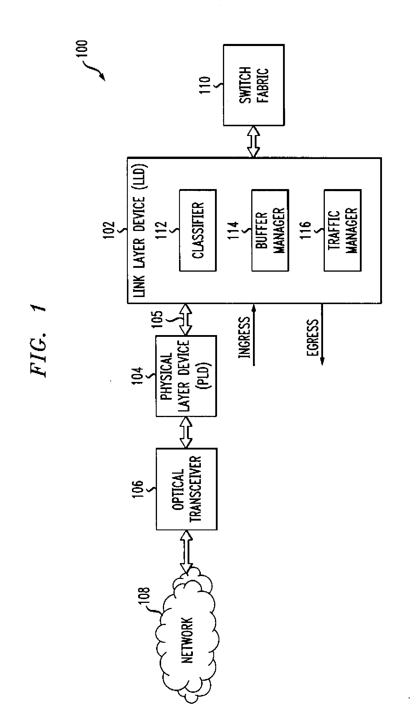
[0026]The invention will be illustrated herein in conjunction with an exemplary network-based communication system which includes a link layer device, a physical layer device and other elements configured in a particular manner. It should be understood, however, that the invention is more generally applicable to any system in which it is desirable to provide improved port addressing as described herein.

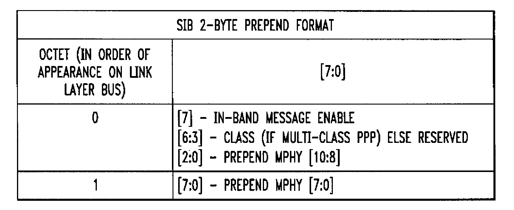
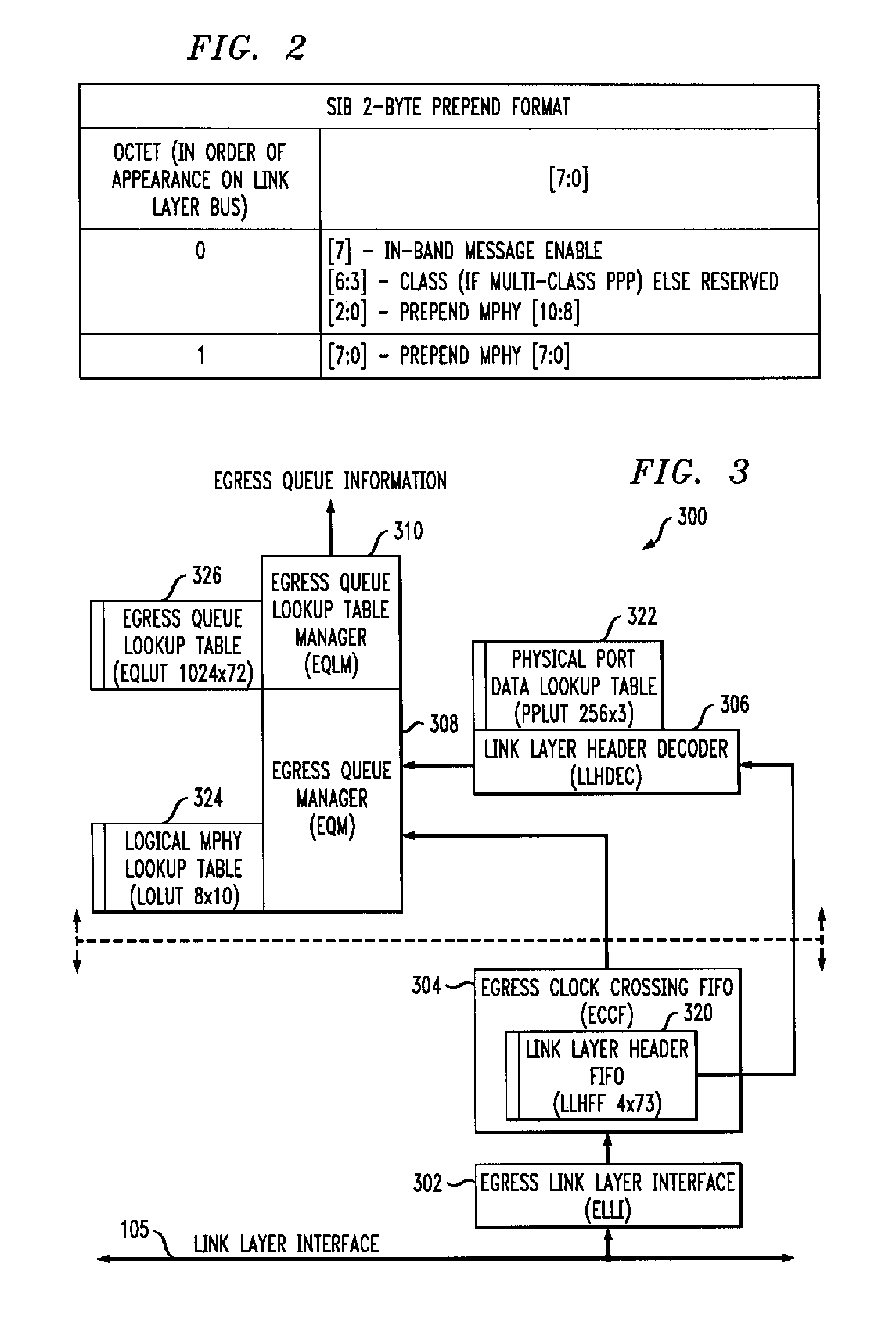
[0027]The term “in-band” as used herein is intended to include, by way of example and without limitation, an arrangement in which additional information is transmitted utilizing an existing standard interface, such as an SPI-3, POS-2 or other similar interface, between a link layer device and a physical layer device, where the additional information is transferred as part of the payload but later dropped after being used for a particular purpose.

[0028]A “link layer device” or LLD as the term is used herein refers generally to a network processor or other type of processor which perfor...


PUM


Abstract

A packet, cell or other data segment received in a physical layer device from a link layer device via an interface bus is processed to determine a port address for the data segment in the physical layer device. The port address, which may be an MPHY address, is determined using a combination of a first address value obtained from a link layer address portion of the data segment and a second address value obtained from a payload portion of the data segment. The data segment is stored in a memory location identified by the port address. The memory location may comprise a particular queue of the physical layer device.

Description

FIELD OF THE INVENTION [0001]The present invention relates generally to communication devices for use in network-based communication systems, and more particularly to port addressing techniques for use in an interface between a physical layer device and a link layer device.BACKGROUND OF THE INVENTION [0002]Current and emerging networks move increasingly diverse traffic types. Such traffic types are also referred to herein as services. In the past, network equipment was dominated by a few traffic types such as time division multiplexed (TDM) or asynchronous transfer mode (ATM). As network applications have expanded, new traffic types such as Internet protocol (IP) must be supported, particularly for equipment at the edge of the network. Since legacy services are still present, networks need to handle multiple services. Such an environment requires multiservice network equipment. It is desirable for cost and other reasons to implement multiservice equipment with devices that can handl...

Claims


Application Information

Patent Timeline
Patent Type & Authority Applications(United States)
IPC IPC(8): H04L12/56
CPCH04L29/12839H04L49/3072H04L69/18H04L49/901H04L61/6022H04L49/90H04L2101/622
Inventor HENRY, ALGERNON P.WHALEN, SHAUN P.WILSON, HAROLD J.
Owner INTEL CORP
Why Eureka
Try Eureka