Network for a cellular communication system and a method of operation therefor

network technology, applied in the field of network for a cellular communication system, can solve the problems of not being practicable to list every underlay cell, not being practicable to extend the current approach to scenarios where the mobile phone is used, so as to facilitate the deployment of a large number of underlay cells, improve addressing, and increase the effect of address spa

Inactive Publication Date: 2010-05-25
GOOGLE TECH HLDG LLC
View PDF9 Cites 83 Cited by
  • Summary
  • Abstract
  • Description
  • Claims
  • Application Information

AI Technical Summary

Benefits of technology

[0014]The invention may provide an improved network for a cellular communication system. In particular, the system may enable or facilitate the deployment of a large number of underlay cells. The invention may allow an improved addressing and a substantially increased address space while achieving efficient routing and management. In particular, the invention may provide a practical, low complexity and / or low cost network comprising a large number of access points that exceed the available address space. The invention may e.g. allow address proxying to be performed at a convenient location and specifically as part of a Core Network. The invention may allow a low complexity address space expansion achieved by functionality having a high degree of compatibility with existing systems and interfaces.
[0015]The invention may allow a practical, reliable and / or efficient system for centrally expanding an available address space by an address proxy. This may for example allow address proxying for a plurality of regions to be concentrated and integrated e.g. in a single network element.

Problems solved by technology

However, underlaying a macrolayer of a 3rd Generation cellular network with a picocell (or microcell) layer raises several issues.
For example, the introduction of a large number of underlay cells creates a number of issues related to the identification of individual underlay cells when e.g. handing over to an underlay call.
In particular, 3rd Generation cellular communication systems are developed based on each cell having a relatively low number of neighbours and extending the current approach to scenarios wherein the mobile phone may need to consider large numbers of potential neighbour cells is not practical.
One problem of extending current approaches to scenarios where there are many underlaying picocells is how to uniquely and efficiently identify a picocell (or microcell).
Specifically, it is not practically feasible to list every underlay cell as a potential neighbour of the macrocell as this would require very large neighbour lists.
These large neighbour lists would e.g. result in the neighbour list exceeding the maximum allowable number of neighbours in the list, slow mobile station measurement performance as a large number of measurements would need to be made etc.
However, sharing identification codes (e.g. scrambling codes) for the pilot signals of the picocells results in a target ambiguity and prevents the mobile station uniquely identifying a potential handover target.
Also, the introduction of a large number of access points / base stations supporting underlay cells introduces a number of issues relating to routing and addressing within such a network.
In particular, the current hierarchical addressing used in cellular communication systems has a very limited address space and does not allow an unlimited number of nodes to be introduced.
In addition, it is important that routing and management operations retain a very high degree of security and mobile authentication which becomes increasingly difficult when needing to accommodate a large number of distributed nodes.
Furthermore, a UMTS system typically has a limit on base station addresses available at each RNC.
However, the approach is unsuitable for systems where the number of nodes at a given level exceeds the address scope for that level.
For example, the introduction of large numbers of base stations / access points supporting very small cells means that the number of cells may exceed the address scope, and it is accordingly not possible to resolve certain addresses within the defined scope.
However, as many tens of thousand residential or enterprise access points may exist in a given network, this substantially exceeds the address space available for RNCs.

Method used


Image

  • Network for a cellular communication system and a method of operation therefor
  • Network for a cellular communication system and a method of operation therefor
  • Network for a cellular communication system and a method of operation therefor

Examples


Embodiment Construction

[0034]The following description focuses on embodiments of the invention applicable to a network for a UMTS cellular communication system and in particular to a system comprising a large number of access points supporting small underlay cells of a macrocell layer. However, it will be appreciated that the invention is not limited to this application but may be applied to many other systems.

[0035]Also the description will focus on embodiments in a circuit switched domain but it will be appreciated that the principles are equally applicable to a packet switched domain.

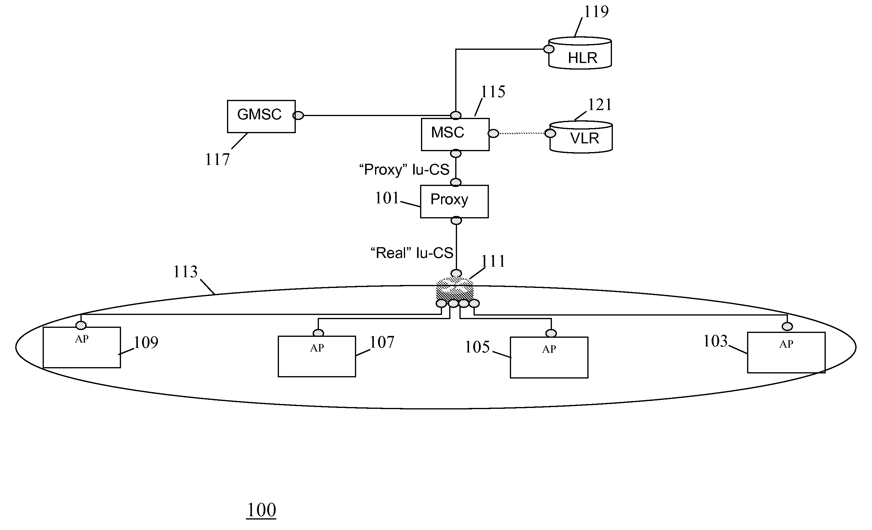
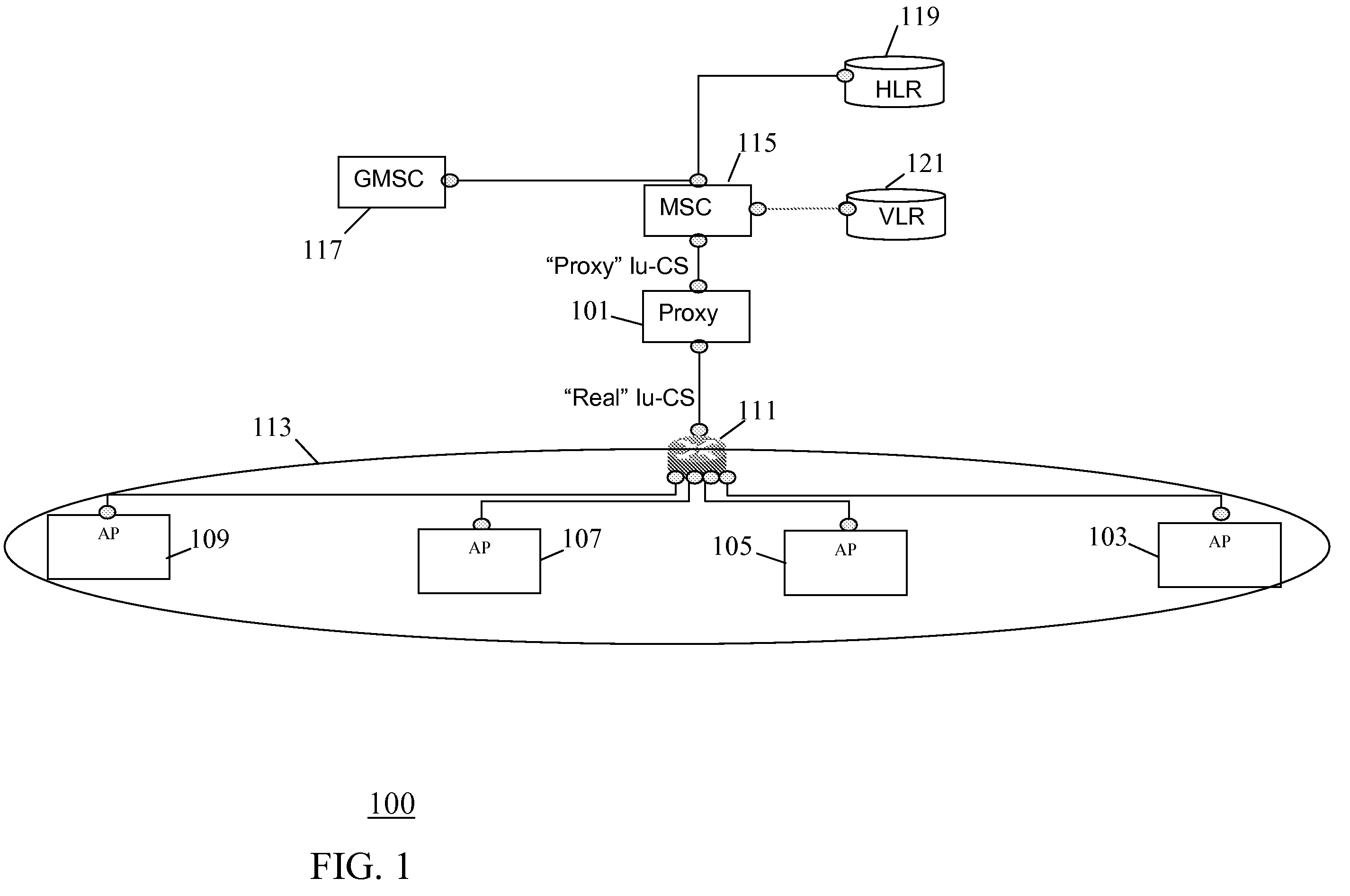
[0036]FIG. 1 illustrates an example of a network in accordance with some embodiments of the invention.

[0037]The network comprises an address proxy 101 which is coupled to a plurality of access points 103-109 via a router 111. In the example, each of the access points 103-109 comprises a UMTS picocell base station (Node B) which supports a small underlay cell of typically around 10-30 meters. Thus, each of the access points...


PUM


Abstract

A network for a cellular communication system comprises access points (105-109) supporting cells within a region (113). Each access point (105-109) has an individual proxy address of a proxy address space which is a local address space of an address proxy (101) and a common network address of a network address space which is a network wide address space. A gateway access point (103) covers an entry point to the region (113) and detects a remote station entering the region. It then determines an access point (105) in the region to which the remote station is handed over and transmits a binding message to the address proxy (101) with an indication of the access point (105). In response to receiving the binding message, the address proxy (101) establishes a binding between the common network address and the proxy address of the access point (105). Data for the remote station is then forwarded to the access point (105) using the binding.

Description

FIELD OF THE INVENTION[0001]The invention relates to a network for a cellular communication system and a method of operation therefor. The cellular communication system may in particular, but not necessarily, be a Universal Mobile Telecommunication System (UMTS).BACKGROUND OF THE INVENTION[0002]A method which has been used to increase the capacity of cellular communication systems is the concept of hierarchical cells wherein a macrocell layer is underlayed by a layer of typically smaller cells having coverage areas within the coverage area of the macrocell. In this way, smaller cells, known as microcells or picocells (or even femtocells), are located within larger macrocells. The microcells and picocells have much smaller coverage thereby allowing a much closer reuse of resources. Frequently, the macrocells are used to provide coverage over a large area, and microcells and picocells are used to provide additional capacity in e.g. densely populated areas and hotspots. Furthermore, pi...

Claims


Application Information

Patent Timeline
Patent Type & Authority Patents(United States)
IPC IPC(8): H04W4/00H04W36/00H04W8/26H04W16/32H04W36/08H04W80/04H04W88/18
CPCH04W36/0033H04W8/26H04W16/32H04W88/182H04W80/04
Inventor FOSTER, GERARD T.IYER, SUBRAMANIAN S.MOORE, BRIAN J.
Owner GOOGLE TECH HLDG LLC
Why Eureka
Try Eureka