Vertebral body replacement implant

a technology for vertebral bodies and implants, applied in the field of vertebral body replacement implants, can solve problems such as increasing clamping for

Active Publication Date: 2012-12-25
AESCULAP AG
View PDF11 Cites 29 Cited by
  • Summary
  • Abstract
  • Description
  • Claims
  • Application Information

AI Technical Summary

Benefits of technology

[0006]The effect achieved by this inclination of the clamping face is that the clamping action is intensified when the two locating parts are pushed together. The result is an additional safeguard against an unintended pressing-together of the two locating parts. Even if the clamping action of the clamping element during the initial fixing of the two locating parts were to prove inadequate or diminish in the course of time, this would lead only to the locating parts moving very slightly closer to one another because, owing to the inclination of the clamping face, this pushing-together would inevitably generate an increase of the clamping force, i.e. the inadequate clamping force that leads to an undesired movement of the two locating parts closer to one another is immediately compensated by this very movement, with the result that the two locating parts in this situation too may move only minimally towards one another.
[0010]In another preferred embodiment, on the other hand, it is provided that the clamping element has a locating face, which faces the clamping face and moves into abutment with the clamping face and which is so small that the locating face, as it is pressed against the clamping face, digs into the clamping face. Such a notch effect leads to a strengthened fixing of the two locating parts relative to one another, the digging of the locating face into the clamping face therefore very effectively preventing the locating parts from moving closer to one another. Either the locating face may be configured to be very small or a very small effective contact surface necessarily arises when the locating face has an inclination differing from that of the clamping face.
[0012]In another preferred embodiment it is provided that the clamping element has a locating face, which faces the clamping face and of which the inclination relative to the displacement path corresponds to the inclination of the clamping face. In this case, therefore, clamping face and locating face have the same inclination relative to the displacement path and, when the clamping element is pressed on, come with their full surface area into mutual abutment. This also leads to a very effective fixing of the two locating parts and reliably prevents an unintended pushing-together of the locating parts.
[0018]It is particularly advantageous if both the locating parts are displaceable telescopically relative to one another along the displacement path.

Problems solved by technology

Even if the clamping action of the clamping element during the initial fixing of the two locating parts were to prove inadequate or diminish in the course of time, this would lead only to the locating parts moving very slightly closer to one another because, owing to the inclination of the clamping face, this pushing-together would inevitably generate an increase of the clamping force, i.e. the inadequate clamping force that leads to an undesired movement of the two locating parts closer to one another is immediately compensated by this very movement, with the result that the two locating parts in this situation too may move only minimally towards one another.

Method used


Image

  • Vertebral body replacement implant
  • Vertebral body replacement implant
  • Vertebral body replacement implant

Examples


Embodiment Construction

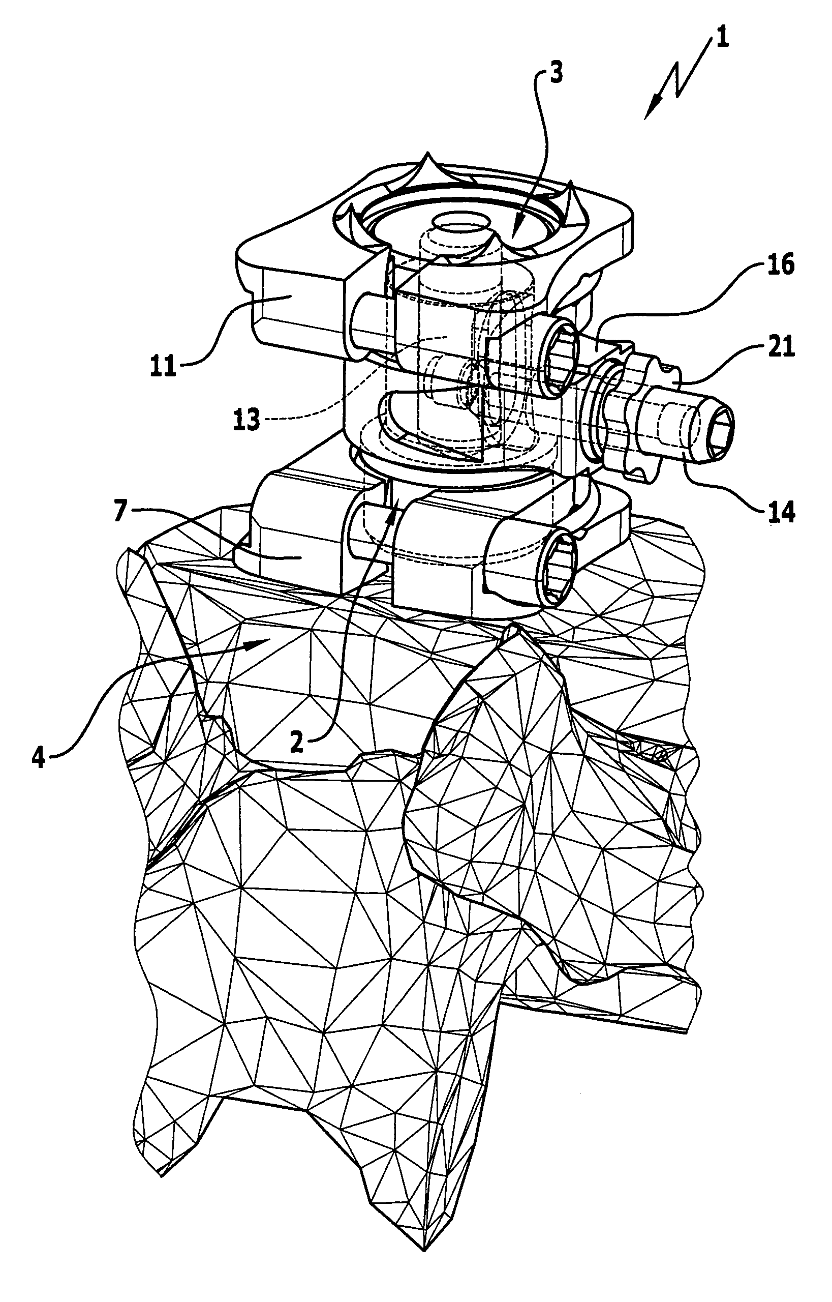
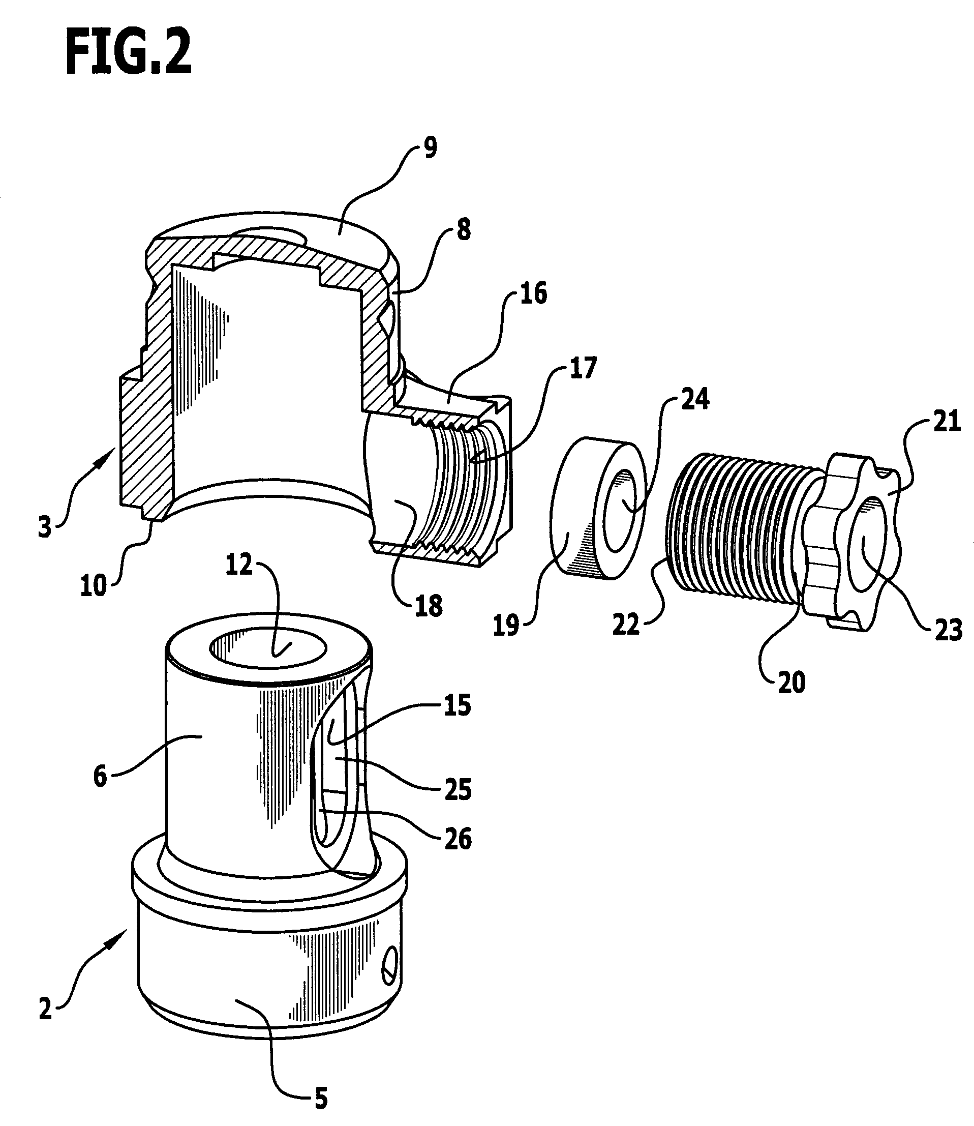
[0025]The vertebral body replacement implant 1 shown in the drawings comprises a bottom locating part 2 and a top locating part 3. The vertebral body replacement implant 1 is intended to replace one or more vertebral bodies and is positioned by its bottom locating part 2 against a lower vertebral body 4 and by its top locating part 3 against an upper vertebral body that is not shown in the drawings. In this way, the two vertebral bodies adjacent to the vertebral body replacement implant 1 may be braced relative to one another.

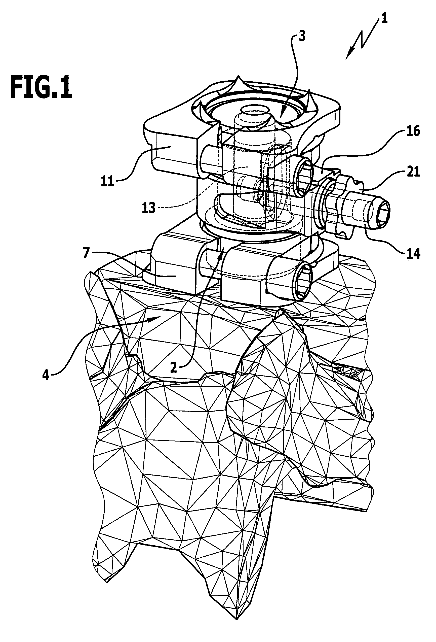
[0026]The bottom locating part 2 comprises a circular-cylindrical base 5 that is adjoined at the top by a circular-cylindrical portion 6, the outside diameter of which is smaller than the outside diameter of the base 5. Fastened to the base 5 is a bottom support plate 7, which is shown only in FIG. 1 and for the sake of greater clarity has been omitted from the representations of FIGS. 2 to 5.

[0027]The top locating part 3 comprises a cylinder 8, which is closed...


PUM


Abstract

In a vertebral body replacement implant having a bottom locating part for positioning against a lower vertebral body and having a top locating part for positioning against an upper vertebral body, wherein both locating parts are steplessly displaceable relative to one another along a displacement path so that the height of the vertebral body replacement implant is variable, having a clamping device for fixing the two locating parts in any desired intermediate position along the displacement path, which clamping device comprises a clamping element that is mounted on one locating part so as to be variable in position and can be pressed towards a clamping face on the other locating part, in order to improve the clamping action it is proposed that the clamping face is inclined slightly relative to the displacement path, so that when the locating parts are pushed together the clamping face moves progressively closer to the clamping element.

Description

[0001]The present disclosure relates to the subject matter disclosed in German patent application 10 2008 006 492.0 of Jan. 29, 2008, which is incorporated herein by reference in its entirety and for all purposes.BACKGROUND OF THE INVENTION[0002]The invention relates to a vertebral body replacement implant having a bottom locating part for positioning against a lower vertebral body and having a top locating part for positioning against an upper vertebral body, wherein both locating parts are steplessly displaceable relative to one another along a displacement path so that the height of the vertebral body replacement implant is variable, having a clamping device for fixing the two locating parts in any desired intermediate position along the displacement path, which clamping device comprises a clamping element that is mounted on one locating part so as to be variable in position and can be pressed towards a clamping face on the other locating part.[0003]Such a vertebral body replacem...

Claims


Application Information

Patent Timeline
Patent Type & Authority Patents(United States)
IPC IPC(8): A61F2/44
CPCA61F2/44A61F2/4611A61F2002/30507A61F2002/3055A61F2002/30601A61F2002/485A61F2220/0025A61F2/484
Inventor LINDNER, STEPHAN
Owner AESCULAP AG
Why Eureka
Try Eureka